The Adcock antenna is two short dipoles fed 180-degrees out-of-phase. When vertically polarized, the Adcock antenna produces a pattern similar to a small loop antenna. The Adcock has better null definition than a loop, and the Adcock includes high angle nulls.
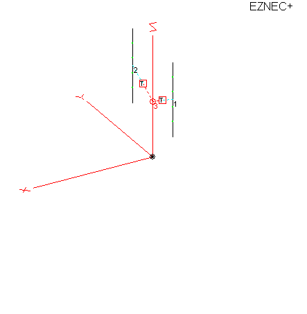
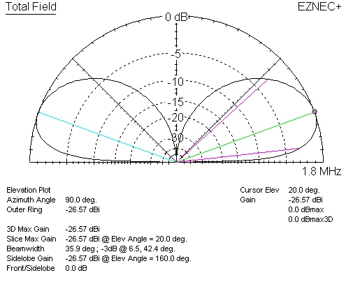
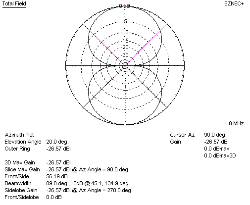
In contrast, a small loop antenna pattern looks like this:
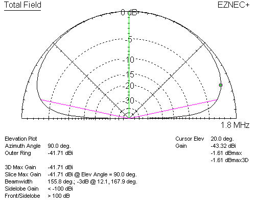
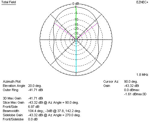
The small loop is good on groundwave or very low angles, but the small loop almost completely lacks useful skywave null definition.
The Adcock, assuming it can be built correctly, has a much better direction finding pattern. The main difficulty in constructing an Adcock is the feed system. Because elements are very high impedance, and because the supporting mast and feed line must enter the Adcock inside the active area of the antenna, common mode can be a problem.
Electrical Rotation
Two loop antennas or two Adcock antennas can be combined through any system that varies relative levels to make the approximate equivalent of a single antenna that can rotate 180-degrees. A goniometer essentially varies ratio of signal levels from the two loop antennas. A potentiometer would do the same thing, except the goniometer has a phase flip of 180-degrees when one current crosses zero level. A potentiometer plus an inversion switch would be the full equivalent of a goniometer.
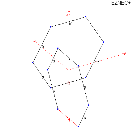
Loop patterns with various current ratios:
0:1 ratio
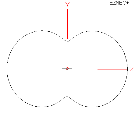
1:3 ratio in-phase:
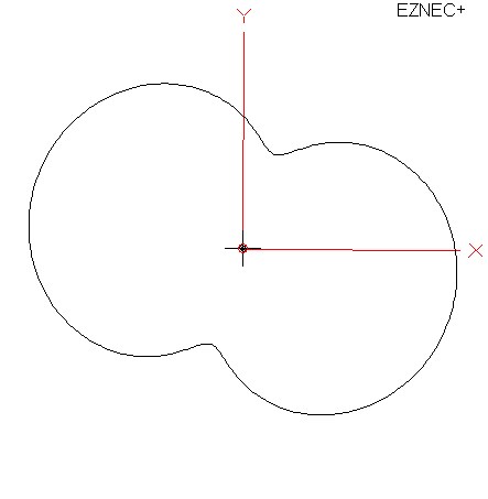
1:1 ratio in-phase:
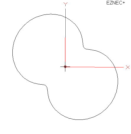
3:1 ratio in-phase:
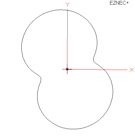
1:0 ratio:
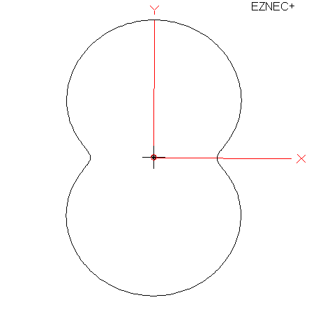
3:1 ratio out-of-phase:
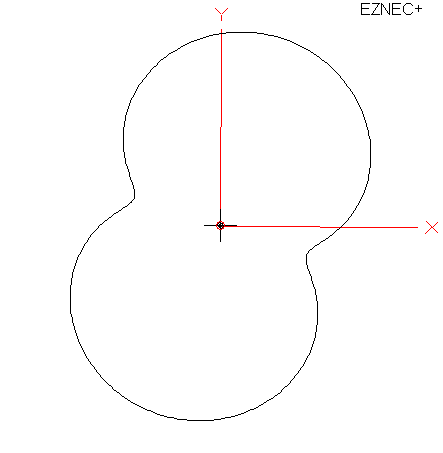
1:1 ratio out-of-phase
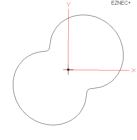
1:3 ratio out-of-phase
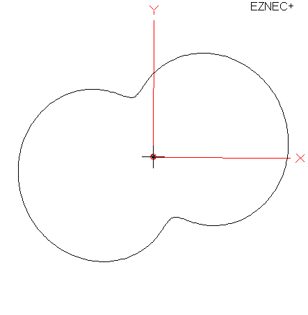
From the patterns above, we find varying amplitude ratio without any phase rotation (other than a hard phase flip when crossing zero amplitude) results in a nulls at any point of 360 degrees bearing.