
A typical vacuum tube radio-frequency amplifier has a high voltage power source. This power source supplies the energy for the RF output power. The vacuum tube acts like a non-linear time-varying resistance in series with a diode. The electrical equivalent of the anode and output system is:
R1 represents the time-varying anode-to-cathode resistance of the output device. As grid-cathode and anode-cathode voltage changes, R1’s value changes.
D1 represents the directional characteristics of the tube anode-to-cathode current path. D1 is always “on” when the voltage at point “A” is more positive than ground. D1 would also behave as a current limiter, the current always having to be something less than the saturated emission current of the cathode. The only exception to this is if the tube shorts or arcs internally.
Let’s examine how this circuit converts DC to RF power. We will assume +HV is 3000 volts.
In
the initial state,
C1 has been charged
through the
following DC path:
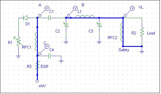
Hopefully the designer was smart enough to include RFC2, to prevent charging or discharging C1 into the load, which might be a sensitive piece of gear (or the operator)!
The voltage across C1 is the anode-to-ground voltage at A, in this case 3000 volts while resting without RF drive power. Everything past A, at B and VL, is zero volts in the resting state. This is because of the low-dc resistance of RFC2 and the nearly infinite resistance (and dc impedance) of capacitor C1. RFC1, the plate choke, establishes a fixed or static magnetic field, the intensity of which is set by the quiescent or steady-state tube idle current flowing through anode-to-cathode resistance R1.
As a positive-going grid-to-cathode RF voltage decreases anode-to-cathode resistance R1, the magnetic flux stored in the inductance of RFC1 tries to hold supply current steady. RFC1 reacts to the current change by increasing voltage across its terminals. Energy stored in the electric field of C1 tries to hold the voltage steady, and C1 sources any additional current the tube (R1) requires as it tries to force C2 and the tank input negative.
The anode, in effect, “tugs” or pulls point A towards ground. The initial peak current can be quite high, limited only by plate-to-cathode resistance, because C1 has a low-reactance (at the operating frequency) path to ground through C2. The tank inductor L1 also builds up a magnetic field, as plate tuning capacitor C2 develops a charge and gradually increasing voltage. This voltage increase comes from the current flowing through C2 and C1 back to the tube. On the initial RF cycle, the voltages hardly change before the grid is moving back negative.
At a time interval equal to 1/(4F) (where F is the RF frequency), the positive grid voltage has peaked. The grid begins to swing negative (or less positive) with respect to the cathode. Anode-cathode resistance (R1) increases in step with decreasing grid-cathode voltage.
There is no power-supply-forced upward swing (the tube cannot source anything). The collapsing field in tank coil L1 (and to a much lesser extent the collapsing field in plate choke RFC1) tries to hold changing anode current at the same value. This is accomplished by the inductances of RFC1 and L1 increasing voltage as tube anode-to-cathode resistance increases. L1 (and to a lesser extent RFC1) pull anode voltage above B+ rail by an amount virtually equal to the amount anode voltage was pulled downwards by the tube, with the anode even more than twice B+ rail voltage under some tank loading conditions!
The actual amount the tank pulls this voltage higher than +HV depends on the amount of energy transferred to the load compared to energy stored in the tank system! This is VERY important in understanding where arcs come from! Some switching power supplies, many ignition coils used in automobiles, and the flyback systems in television receivers use this type of "flyback effect" voltage to step up voltages to very high levels without use of transformer action.
This cycle repeats over and over. Assuming the tank system at C2, L1, and C3 is resonant, voltage at point A increases in alternating swing while the peak current through R1 (the tube) is gradually reduced. Eventually, in a fully loaded amplifier, equilibrium is reached. In a properly tuned amplifier running at maximum available power, equilibrium occurs when point “A” swings up and down an amount just under twice the anode DC voltage.
Consider a class AB 3-500Z using a 3000-volt supply. When the amplifier is tuned into the load properly at full rated power, and driven to full power, anode voltage will swing between 5,500 volts maximum and 500 volts minimum at point A. This would be a total anode voltage swing of 5,000 volts. Peak instantaneous anode current in continuous carrier operation would typically be 1.12 amperes, with a minimum R1 value of 446 ohms. This is typical of continuous CW power out of 750 watts with a single 3-500Z tube with a 190-degree conduction angle running at 400mA average anode current from the HV supply.
Let’s assume (we actually CAN have this condition, if the amplifier and exciter relays are not sequenced correctly) we have an envelope that rises instantly. At the peak of first positive grid-cathode cycle, the anode resistance would drop to someplace well under 400 ohms (anode resistance is non-linear with anode voltage, and is lower with higher anode voltages). The saturated anode current could reach 7.5 amperes in the 3-500Z, if tube grid-cathode bias permits.
(Emission in a directly heated thoriated-tungsten tube is typically in the range of 50-100mA per watt of heater power, large transmitting tubes being at the upper end of that range. A full-emission 3-500Z has a saturated emission current of about 7.5 amperes.)
If we have infinitely fast envelope rise and fall times from the exciter, amplifier RF-envelope rise and fall times are determined by the operating Q of the tank system. C2/L1/C3 dominate the high frequency energy storage. RFC1 and C1, being larger values, dominate lower-frequency energy storage, while stored energy in the power supply dominates long-term energy demands. The voltage across C2, upon initial application of RF drive, is a rapidly expanding sine wave. It reaches maximum steady-state swing many dozens or hundreds of RF cycles later than the initial tube excitation (and decaying in a similar fashion).
The
peak voltage across
C2 is equal to the
peak anode voltage
swing, and the
peak-to-peak voltage is
slightly less than
twice the HV supply
voltage in NORMAL
operation. The
voltage across C3 is
a function of the
load resistance, and
power delivered to
the load.
| SWR or Reflected Power Myth: We often hear people claim reflected power burns up as heat in the power amplifier stage. This is not true at all. The only effect of reflected power is it changes the loadline of the output device. This can either increase PA device RF voltage swing, or it can increase PA device current. If the voltage increases heat generally is reduced, but the PA can arc. If the load mismatch is of a phase angle that increases current, PA device heating increases because conduction angle and peak current increases. In one case heat increases, in the other heat decreases. An SWR mismatch only requires the matching network be readjusted to restore the proper loadline at the output device. In an adjustable pi-network or pi-L network system the only effect of SWR is in current in the inductor(s) and voltage across the loading capacitor, so long as the network can be adjusted to proper load at the output device. in other words if you can retune the network and don't exceed voltage breakdown of the loading capacitor, your amplifier is very likely OK for any SWR. |
We know the tank circuit stores energy. We now understand the conversion process where DC is converted to AC (or RF) power. We also must understand energy must be transferred out of the tank at a rate equal to or exceeding the rate at which it is supplied by the downward “pull” of the tube. If we do not remove energy at a sufficient rate, voltages and currents increase until a new point of equilibrium is reached. Voltage at point “A” can actually swing well beyond twice +HV on upward excursions, and below zero volts (becoming negative) on downward excursions.
The maximum voltage with a load or drive fault can be tremendously higher under the fault condition than typical properly operating tank working voltages (when energy is being removed at the proper rate). If we do not remove energy from the tank at the same rate the power supply is supplying energy, the voltage in the tank will increase until something absorbs that energy!
We have the same basic tank system as discussed earlier, but with light loading compared to drive level the tank is pulled down very hard by the tube. Minimum Rp is reached early in the cycle, before the tank voltage reaches it’s minimum swing. This is easy to do, since the tube only pulls the system down and the tank stores the energy of that downward tug.
As the plate voltage swings below zero (negative) from the tank energy, the tube is already cutting off. Nothing clamps or prevents point A from going negative. D1 effectively takes the tube out of the circuit. By the time the tank reaches it’s minimum, the tube’s grid-cathode voltage is already on its way positive. The tank free wheels positive, and can overshoot the +HV supply by several times the supply voltage. If loading is light enough and Q is high enough, this continues until the energy stored in the tank reaches equilibrium with energy transferred to the load, or a component fails and the arc dampens the tanks gyrations.
See the practical demonstration page for a real working model with waveforms!
Since the anode-to-cathode resistance of the tube varies over the RF cycle, how do we establish the plate resistance of the tube? It all goes back to energy transfer. We must extract the same energy available from the power supply power drawn by the time-varying tube resistance, less any dissipation in the tube or loss in the tank components. Otherwise the anode voltage swing will not be in equilibrium, voltage swing will continue to build until something eventually extracts the energy at the same rate as it is applied.
If we try to extract too much power to the load compared to the optimum value, the output device current will increase. The tube path looks like this:
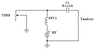
The tank circuit transforms the load impedance of the antenna system or dummy load up to a new value. This resistance appears at C1, and is coupled through C1 to the tube and power supply junction. This is the resistance value we are actually calculating when we plan the plate resistance, Rp.
This resistance has to match the optimum E/I of the desired RF frequency appearing at the anode of the tube. Let's consider the fundamental frequency only in a typical class AB amplifier operating near the class B end of the operating point. Let's assume we have 3000 volts of high voltage, and the tube performs best swinging down from 3000 volts to 500 volts. This is 2500 volts of peak anode voltage swing, and the flyback effect causes the anode to reach 3,000 (B+ value) + 2,500 (downward swing) = 5,500 volts on peak. Our vacuum tube has a peak dc anode voltage of 5,500 volts in NORMAL linear operation. If you develop an antenna system problem or have a bad lightning arrestor or relay, the peak voltage could be several times that amount.
| I've seen test data from Chinese 572B's where the tubes were tested for
arcing and failure at 1,500 volts dc anode voltage. If we think
about this, all
tubes should be
tested to
withstand some significant amount more than twice the
maximum dc anode
voltage.
This is a
noteworthy point
because test
data from
various Chinese
manufacturers
has indicated
they test tubes
at less than the
rated dc supply
voltage. Manufacturers should
actually be
testing and gettering tubes
to withstand
significantly
more than twice
the highest
expected dc
supply voltage.
Even an
811A should not
be tested that low. The old Eimac
3-500Z's, rated
at 4,000 volts
supply voltage,
used to test to
over 12,000
volts of
anode-to-grid
breakdown
voltage. They
virtually never
arced when new. To be reliable an 811A tube should hold off nearly 5 kV with minimal leakage and no sign of arcing. A 572B should hold off over 8,000 volts. |
With the 3-500Z example, we might have a useful RF output power of 800 watts with the anode swinging 2500 volts peak (5000 volts p-p), or about 1700 volts RMS at the fundamental. There are harmonics involved, so to do this right we would have to use a Fourier (harmonic waveform) analysis of the waveform, and there is just such an analysis that was developed for vacuum tubes called a Chaffee analysis, but for casual use we can use approximations. The typical rule of thumb for tubes with a 15% minimum plate voltage is we multiply indicated anode current by 1.6, and use the supply voltage. Ep/(Ip*1.6) = Rp. Using this example we have 3,000/(.4*1.6) = 4,688 ohms.
Now let's look at another rough method. We know the swing is about 2500 volts, so RMS is about .7 times that. 1750^2 / 750 = 4,083 ohms.
Using a Chaffee analysis the optimum load resistance comes out to 4500 ohms. The error in approximations is in not allowing for harmonic content.
We often get far too worried about tank circuit Q. There really is very little change in efficiency as Q moves from a minimum of (SQRT Rp/Rl)+1. If we had a 4500 ohm optimum anode load resistance (Rp) and a minimum load resistance of 25 ohms, we would want a tank Q of at least SQRT 4500/25= 13.4 + 1 = 14.4. A typical HF tank circuit, even with modest sized components and such a large impedance ratio, only has approximately 4 % power loss. If we doubled the Q, tank loss would only be 8 %. Lower impedance ratio tanks have even less loss and are less worrisome.
Most of the power loss is in the conduction angle and waveform shape of the tube, not tank Q. It is certainly not in a blocking capacitor, would would overheat and disintegrate if it had more than a tiny fraction of just one percent loss.
Don't get overly concerned about Q. Most of the time you will be off 20-30% anyway. Handbook formulas for Q and Rp are just rough approximations, and loaded-Q generally has a small effect on overall efficiency (unless the tank components have a great deal of loss).
The efficiency of a power amplifier can be well over 50% even when the amplifier's output port is conjugate matched to the load. This is because the output device can switch on and off hard, and not be in a state where it looks lie a dissipative resistance very long. The tank circuit filters the sharp transitions out, and rounds the waveform into a sine wave. At this point we have an optimum across and through vector, voltage across the tank and current through the tank, and that is the "impedance" conjugate matched to the load. The only dissipative part of the system, other than small tank and circuit losses, is the tube or output device. Since that area is non-linear (not in transfer function, but in fractional cycle linearity) power conversion efficiency can be quite high.
As an example of this I measured the output impedance of a pair of class-C 6146's two ways, by using a traditional load pull and by using a reverse power generator and a tapped line. When tuned for maximum efficiency at full power, the output port looked very close to being a 50-ohm source. Despite being a 50-ohm source, efficiency was around 80%! As a matter of fact I measured over a dozen PA systems and all of them produced near-maximum efficiency and an efficiency of over 50% while they behaved like a true 50-ohm source.
An amplifier does not need to be conjugate matched to work, and indeed many or most are not conjugate matched, but they are when tuned for maximum efficiency!
To have high efficiency conduction angle must be as short as possible, and when the output device turns off (goes open circuit) the output device must transition into open circuit as rapidly as possible. This is why a low-pass tuned input is so necessary for maximum efficiency in a grounded grid amplifier.
Contrary to somewhat popular myth, reflected power does not heat the power amplifier. As a matter of fact reflected power can actually make the PA stage run cooler! The only effect of load mismatch is the operating load line presented to the output device by the tank circuit shifts to a different value. Normally, an adjustable tank has enough range to correct the load line change. Even if the SWR is 10:1, if the tank adjustment range allows adjustment to normal grid and anode currents and proper RF power levels, efficiency and heating will not change.
If tank range is insufficient for the impedance presented to the PA by the feed line, or if the PA stage is "fix tuned" and lacks any ability to readjust to a new load impedance value, the load line will shift. To the tube or output device, this is not any different than mistuning the tank. This is why non-adjustable systems, like typical solid state PA's, require a low "load SWR". Because the tank cannot readjust, they must see the design impedance. This is typically 50 j0 ohms.
If loadline impedance decreases, the output device's current will increase. The current increases while peak output device voltage is reduced, and the anode current conduction angle increases. The longer time period of increased current result is more anode heat. This can result in an anode thermal failure, if the time and dissipation product exceeds safe limits.
If the loadline changes in a way that reduces anode current, less anode heating occurs. The output device runs cooler, but peak voltage increases. If peak voltage exceeds safe limits, an instantaneous failure will occur.
Tube-type amateur transmitters were often rated for a very wide load impedance range. This shows the fallacy of thinking feed line reflected power causes a PA to overheat.