It takes a special meter to measure current accurately in the presence of strong electric fields, and to not disturb low-capacitance high impedance systems. The meter described below is suitable for measuring RF current accurately in high voltage applications, such as short antennas. It is also accurate in normal applications
Another current meter project link (not suitable for mobile antenna measurements, however!)
http://www.ifwtech.co.uk/g3sek/clip-on/clip-on.htm
Low Capacitance, Voltage Immune, RF Current Meter
The meter is constructed with a 100uA all plastic case meter. The meter scale is plastic. The movement and all metallic areas are small. The lack of large metallic components minimizes stray capacitance added to the circuit under test by the proximity of the current meter.
Low capacitance ensures the meter has the least possible effect on the circuit being tested.
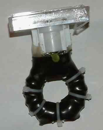
This meter has a 1.5" toroid current transformer on the rear. Just behind the meter is a calibration pot and all the circuitry. The toroid and circuitry is hot-melt glued to the meter with only the screwdriver calibration pot exposed.
I did not add a Faraday shield because the shield would increase the capacitance. Since this entire meter floats above ground there is no need for a shield. Balance is not critical when the load is physically very small and floats from ground because common mode impedance is very high.

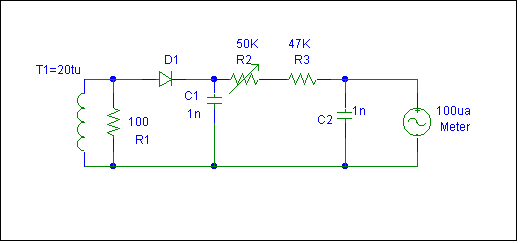
The meter has a low threshold Schottky diode detector, a series resistor for calibration, and standard .1uF bypass capacitors.

T1 is a current transformer. I used a powdered iron T150-2 core. When the single turn primary (a whip or mast) has 1 ampere, the secondary will have .05 amperes (inverse of the turns ratio). R1 flattens the response and limits the voltage.
It turned out that 100 ohms gave the flattest response from 1.8 to 30 MHz, which is the frequency range I intend to use the meter on. With 100 ohms we have .05*100=5 volts RMS. The peak dc voltage is 1.414 times 5= ~7 volts. C1 is a filter capacitor for the RF pulses, R2 and R3 set the FS range. With 100uA meter the resistance is 10,000 ohms/volt. 7 volts requires 70K ohms, which will be approximately midway on R2.
Note the choice of a low current meter and >50k multiplier resistance. The low current and high voltage improves detector linearity.
Dissipation in R1 is .25 watts from .05 amperes (T1 current) times 5-Vrms (secondary voltage of 5v with .05a flowing through 100 ohms).
Calibration
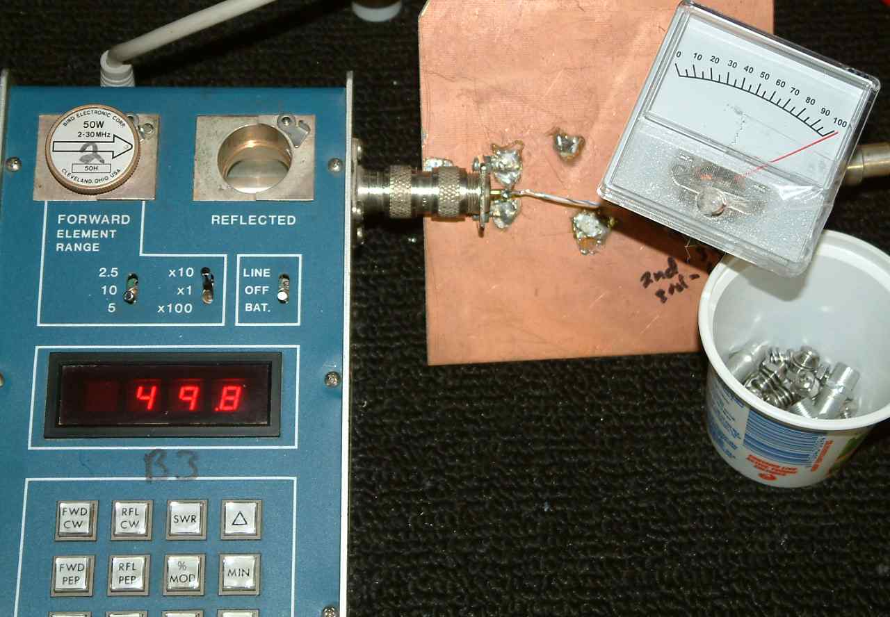
The meter is tracked in a test fixture for linearity. The actual fixture used is shown below.

The test fixture consists of two UHF female connectors soldered to a sheet of PC board. There is a single #16 Teflon wire running between the center pins.
Note the numbers "2" and "B3" on the meters. My elements and meters have calibration charts that correct for linearity errors in tracking and readings. In this case I've applied 50 watts to a precision 50 ohm load, making wire current 1-ampere.
The meter is calibrated and scale was tracked from 1 ampere down to .2 amperes.
FS accuracy is not required in comparison measurements, since the meter references against itself. Linearity within a few percent is important.
This type of meter is much more reliable and linear than thermocouple RF ammeters, and perturbs systems much less. Stray capacitance added to the system being tested is very small, because only the proximity of the meter and the compact wiring area. Contrast that to actually connecting a meter in the line with the associated lead lengths and capacitance of the meter itself, and the advantages of a transformer coupled meter become apparent.