Capture Area Ae effective aperture
|
Capture Area Ae effective aperture |
|
Capture area, or effective aperture, is one of the most misunderstood antenna system terms. In amateur radio or layman antenna theory, capture area or effective aperture is often used to justify unjustifiable fantasy antennas. Looking carefully we find capture area or effective aperture used to justify totally absurd claims in systems that promise great advantage where none exists. Capture area or effective aperture has a use in antenna theory. Let's look at what capture area or effective aperture means and what it can be used for, and where and how it is misused. What is Capture Area?Capture area, or more correctly effective aperture (Ae), is a direct function of antenna gain and operating wavelength. Ae is determined by the voltage available across a load matching the antenna feed impedance for a given electromagnetic field strength density. In simple terms if the antenna is placed in a electromagnetic field of a certain intensity, a certain amount of power will appear in the load at the antenna terminals. The area of space around the antenna that provided this amount of power is the effective aperture. Many people confuse physical area, or Ap, with effective aperture. They are not the same. Physical size only determines effective aperture as physical size might affect gain of an antenna. Gain and wavelength determines capture area, but capture area itself has nothing to do with actual physical size or physical area of the antenna. For example a 1/2 wave long dipole in freespace has a capture area of about .13λ². This means a lossless freespace dipole has an Ae of approximately .13 square wavelengths. This effective aperture is about 100 times larger than the actual physical area of a thin wire dipole antenna. Energy is extracted from an elliptically shaped area slightly longer than the dipole and about 1/4 wave diameter at the center. This is why increasing conductor diameter or using a cage of wires will not increase electrical aperture or capture area. As a matter of fact if we built a lossless or very low loss small dipole, perhaps λ/20 (1/20th of a wavelength) long, capture area or Ae would be within a few percent of a full size dipole! A change in antenna element diameter does not affect gain, except as it might very slightly reduce power losses in conductor resistance. Length itself has very little effect unless the change in length significantly affects antenna gain. We must have a change in gain to change Ae (effective electrical aperture). Physical aperture (Ap) changes do not affect Ae unless the gain changes.
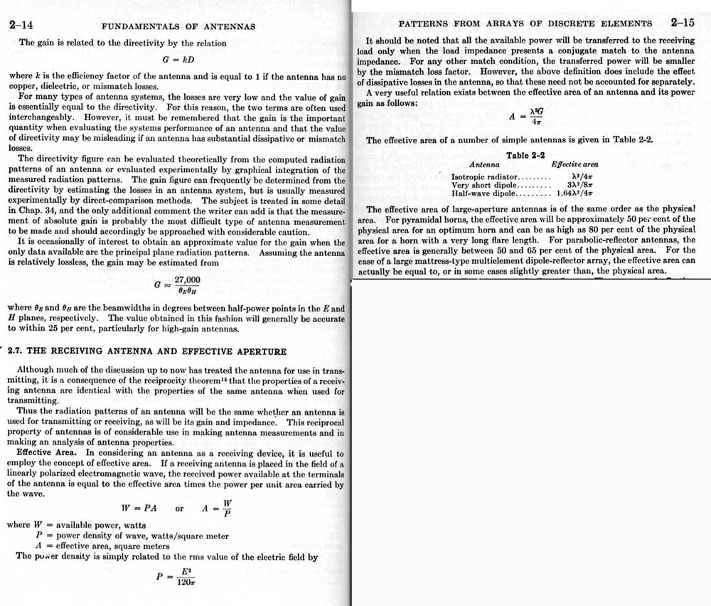
From the Antenna Engineering handbook by Jasik we have:
We see from the beginning of text above that gain, absent significant losses in the antenna, is equal to directivity of the antenna. This is another way of saying something we all should know and remember. It is impossible to have antenna gain without having a more directional pattern. In order to increase gain, an antenna must focus more and more in certain directions and radiate less signal in other directions. Always. The only exception is when a lossy reference antenna is compared to a much lower loss antenna. Virtually all dipoles are in the upper 90% efficiency range. Properly installed dipoles make an excellent reference antenna. From the text in 2.7 above we learn effective aperture is directly related to gain and operating wavelength of the system, nothing else. Physical size does not enter the equation, nor does conductor surface area. While certain very large antennas with very low loss may have a rough relationship between physical area and effective aperture, that relationship is more coincidental than a rule with typical antennas we use. Only certain structures, like parabolic reflector antennas, horn antennas, and mattress arrays, approach a 1:1 effective aperture to physical aperture relationship. Using equations derived from or embedded in the above engineering text , we find the following effective apertures or capture areas:
Or using Ae = λ²G/4π where G is the "multiplication" (not in dB) we have .13λ² for a dipole. We often hear a quad antenna "receives weak signals better" than a Yagi or dipole because the quad "has more capture area". Yet the basic quad element, despite being touted as a huge capture area antenna, only has about 28% more capture area than a short dipole. This is because the quad element in freespace under ideal conditions has about 28% more gain than a dipole! This ~28% increase is only under ideal case of a single quad element in free space compared to a dipole in free space. When multiple elements are added (to make a cubical quad antenna or a Yagi antenna), or even when the dipole and quad antenna elements are placed over earth, the 28% difference in capture area decreases significantly! In many cases the dipole or Yagi winds up with more capture area than a similarly located quad antenna, but for most cases of well-built antennas with similar boom lengths the Quad and Yagi are equal in gain and capture area. The increase in capture area of a single quad element over a dipole has nothing to do with the 600 fold increase of space enclosed inside the antenna's area. The increased capture area ties directly into the change in gain, the loop having about 1.1 dB gain over the dipole under ideal conditions. The loop's 2 dBd gain figure bantered about is actually wrong. The 2 dB figure came from flawed measurements made on UHF way back in the 1950's. Back then UHF equipment and UHF measurement techniques were poor. This resulted in a measurement error that was published in several places and initially accepted as fact. Once published (even if later corrected), the bad information keeps reappearing. Despite being corrected we are likely to keep seeing the 2 dB figure for the rest of our lives, even though the correct figure is 1.1 dBd for a free space single element quad antenna and even less for a quad over earth or a multi-element cubical quad. |