Stab position and setting up installed timing
Rotor phasing (alignment of rotor to post contact)
Plug Wires
A quick word about plug wiring. Never dress spark plug wires from high energy ignitions in a bundle. Electric field and magnetic field coupling can cause enough cross-talk to spark an unwanted plug even with good wires. Never dress two adjacent distributor post wires next to each other for any distance. For example, in a 1-3-7-2-6-5-4-8 Ford firing order, never dress wires 1 and 3 or wires 6 and 5 next to each other for any distance. The reason for this is simple. If adjacent post wires ever cross-talk, you can fire a cylinder 90 degrees ahead of time. Cross-firing adjacent posts can be a worse case scenario, firing a cylinder while the cylinder is full of unburned fuel and air (and soon to be on the way up). Adjacent firing cylinders are 90 degrees out of phase mechanically. With 20 degrees running spark advance, a cross fire can ignite a the next cylinder with 110 degrees spark advance! That much advance is never good at high speeds.
Resistance is generally a very poor way to test wires. Most meters measure resistance with voltages well below 9 volts. The spark is thousands of times higher voltage! An open wire or high resistance at 9 volts can behave perfectly at 20kV, and a low-ohm wire test can behave poorly. Although high resistance conductors should be avoided, resistance measurements with typical low voltage meters actually have very little to do with high voltage wire performance. A simple meter test will neither guarantee a wire is bad or good! A visual inspection for cracks, holes, or burns is actually much more reliable than a meter. Unless you have a proper tester or know how to test visually, if you have any doubts about wire condition, change them.
Distributors
There is a lot of misinformation about distributors. One myth is that the distributor position in the block, or the particular tooth in the block, determines timing and rotor sync. Some people even claim they move the distributor one tooth and pick up speed or ET, or the car pulls better.
I'll show you why, even though some claim things like that, it cannot be correct for any distributor system that has the ignition spark timing pickup or trigger located inside the distributor. While this is specifically about the common Ford TFI system, system basics also apply to most other systems.
My experience with ignitions started early. In the early 1960's, I hand built a tachometer and solid state ignition for my dad's 1957 Ford. While still driven by the points, and still using the stock coil, four early transistors reduced the point current. I just wanted to see how power transistors would work in ignitions, since they were starting to appear in some car radios.
TFI Thick Film Ignition Mounting
The TFI is a module that replaces the electrical function of breaker points. The TFI module is nothing but a solid state off-and-on switch controlled by a small signal.
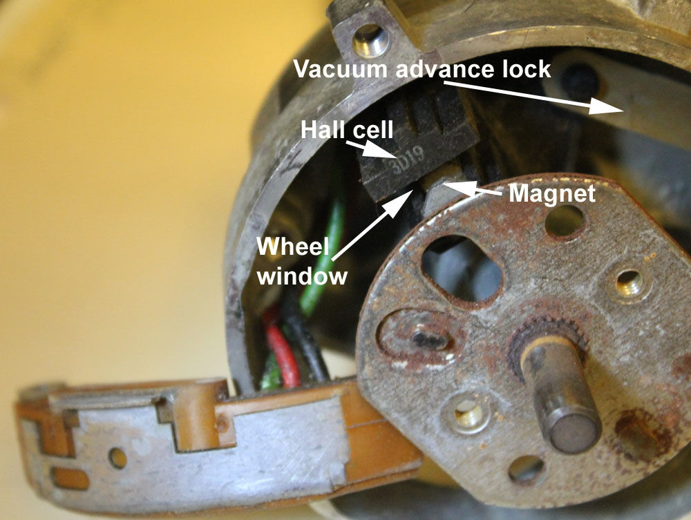
In early Ford computer systems (before crank trigger systems), a shutter wheel interrupts the flux path of a small permanent magnet to a Hall effect cell. The path interruption by the steel blade of a shutter wheel changes the Hall cell's conduction state.
The computer looks at this voltage, which is called the PIP (profiled ignition pickup) signal. This signal replaces the mechanical cam on a breaker points distributor. The computer rapidly and continually learns the sequence of the pulses, smoothing them while also learning number one pulse postion, and then modifies the timing of evenly-spaced, but much longer, pulses sent to the TFI module.
The TFI replaces the metal contacts on "points", which are an electrical equivalent of the old mechanical cam operated normally closed switch contacts in breaker points. The TFI is closed, just like breaker points, when the computer supplies an ignition dwell signal. The steady dwell current, just as with old points systems, builds a magnetic field in the ignition coil core.
The dwell signal disappears at the moment the computer wants spark. This removes coil magnetic charging and field holding current. The collapsing magnetic field causes an extremely high secondary voltage. We could accurately say this is a magnetic discharge system, as opposed to a capacitor discharge system.
Because it is a magnetic storage system, and not a capacitor storage system, the coil operation is much different. Because the operation is different, optimum coil design has to be much different.
Most of the current limiting is in the ignition coil. A bad coil or the wrong coil is extremely rough on the the TFI module.
When steady direct current voltages are applied to inductors, current will build. Eventually current reaches a maximum value that is limited by static and dynamic resistances. Heat is always current squared times resistance, so heat is produced by current through the resistance. Every bit of operating heat produced inside the TFI module, and in the ignition coil, is caused by resistances and average current through those resistances.
Current while "charging" the coil is primarily limited by coil inductance, and not by resistance. While inductance does not contribute to coil heating, it does limit TFI current through much of the field charging (dwell) cycle. Shorted turns, or the wrong coil (too low of inductance), will increase TFI heating by increasing dwell current. An ohmmeter is not a good test of ignition coil functionality. Shorted turns, or the wrong coil (too low of inductance), can increase TFI heating without showing on an ohmmeter.
If the TFI module did not have some current limiting, it would generate no more than 5-10 watts of heat. The TFI module has some current limiting that functions like old-time ballast resistors and ballast wiring. This resistance causes additional heating in the TFI module. The TFI module generates most of the heat at idle or low speeds. This is because the "on" (dwell) duty cycle is highest, while current limiting effects of inductance (which does not produce heat) is lowest.
The conventional Ford distributor with TFI module depends heavily on engine fan airflow for cooling. Altering airflow in any way that reduces air across the engine front and across the distributor will increase TFI module temperature.
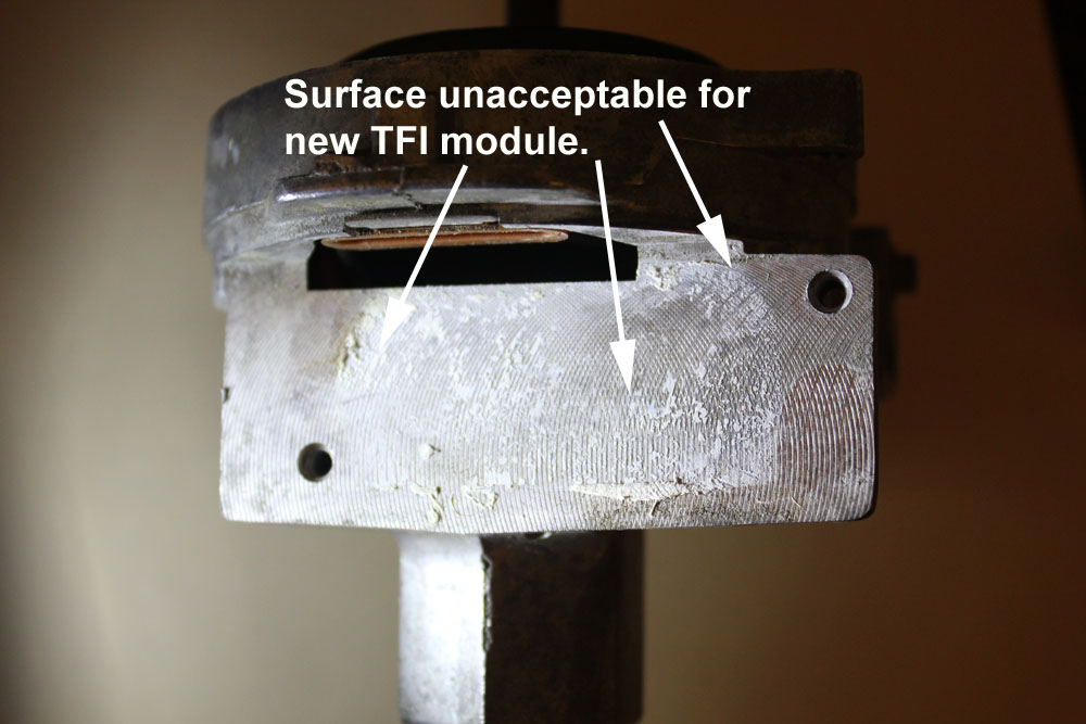
The TFI module surface looks like this:
The above surface is unacceptable. The lumpy, dirty, surface will prevent the module from having good contact. This will cause the module to run hotter.
Cleaning the surface with a light solvent, such as 100% alcohol, lacquer thinner, mineral spirits, or almost any fast evaporating paint thinner, will remove the old, dry, lumpy, thermal compound. A clean surface, ready for a new TFI module, should look like this:
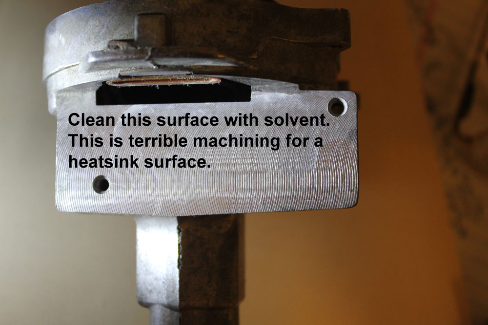
Ford, for some reason, does not machine the surface very well. Because air insulates heat, the surface requires a **thin** layer of heatsink compound or pure silicone dielectric compound between the clean TFI module surface and clean distributor surface. Contrary to Internet rumors, pure silicone dielectric compounds work almost as well as dedicated heat sink compounds. The grease functions to fill ridges, displacing any trapped air that would thermally insulate the module from the distributor. The grease has to be able to work down into the grooves and push air out. A thick layer of thick compound is actually as bad as no compound at all.
Do not use too much compound. Use just enough to fill the grooves fully. Nothing will transfer heat out of the module than direct metal to metal contact. Heat sink compound, although much better than air gaps, still has several times the thermal resistance of metal-to-metal contact.
For best life:
Clean the surfaces
The TFI module will NOT cause a PIP module failure, and a PIP module failure will not cause a TFI module failure. The PIP wiring just passes through the TFI to reach the wiring harness without any important connections to TFI module electronics.
The PIP system uses a Hall cell sensor. A shutter wheel interrupts the magnetic field from the magnet to the Hall cell. The block circuit is:
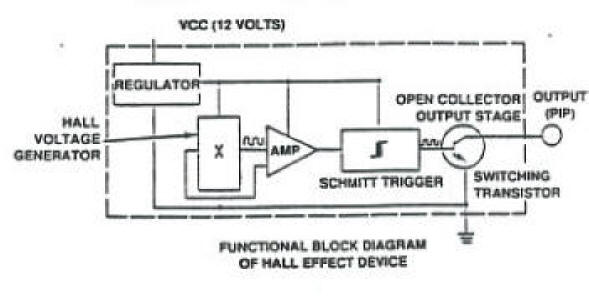
The functional description is:
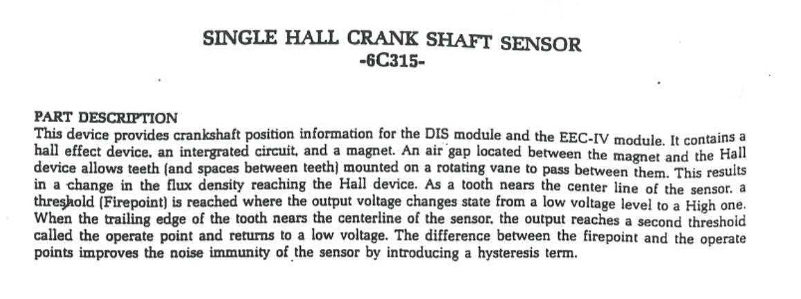
The PIP triggers a timing reference signal as any wheel tooth enters the center area of the cell-to-magnet shutter wheel gap.
If the magnet loads up with iron trash, timing will become erratic. Enough trash can cause random PIP failure, shutting the computer down.
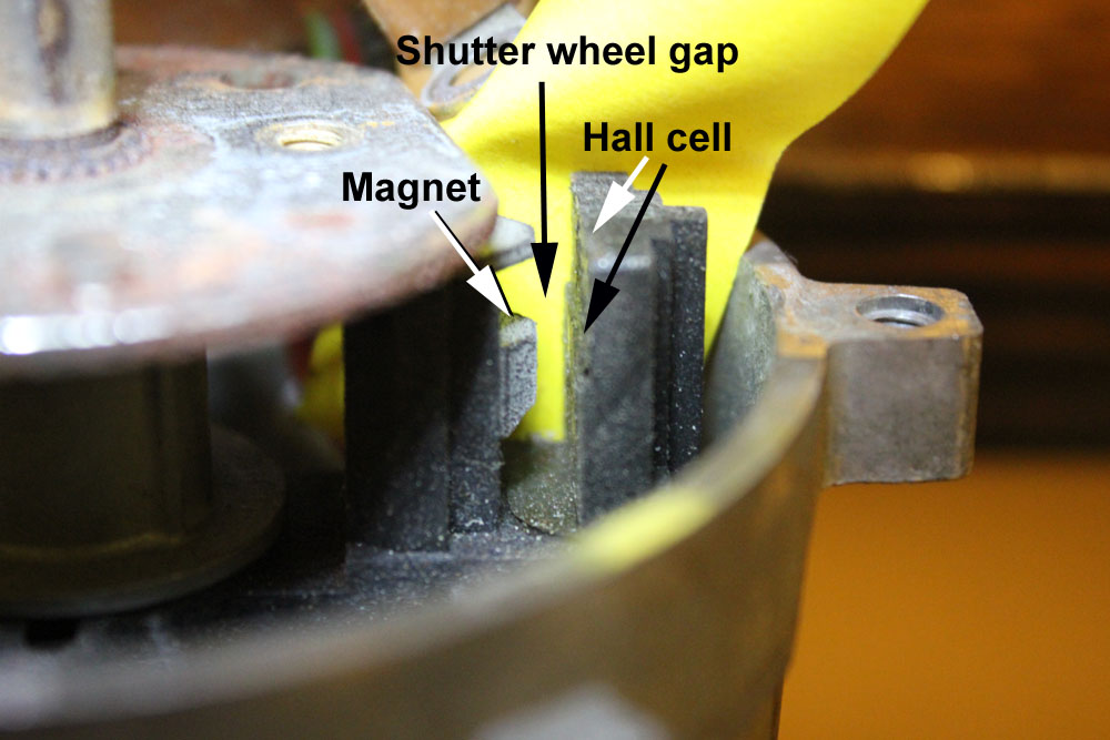
The wheel looks like this. The firing order is for the 302 HO camshaft:
The actual wheel pattern looks like this. All teeth except 1 are the same size:
This drawing is for a standard HO firing order of 1-3-7-2-6-5-4-8. This would be a view from the hall cell side of the distributor.
PIP triggers (the leading end of the wheel teeth) occur exactly 45 distributor degrees from each other, for a total of 360 distributor degrees. Since the distributor turns at half crankshaft speed, firing pulses occur every 90 crankshaft degrees.
Trigger edges, even for narrow tooth number 1, are all exactly the same distance apart. Only the trailing edge of number 1 changes. Decreasing #1 tooth width increases the shutter wheel air gap to cylinder three, which increases Hall cell dwell time after number 1 blocking tooth clears.
Notice the number 1 trigger tooth is narrower, causing a wide gap after the number eight trigger edge before the PIP's dwell. The computer watches for a longer open window to learn when number 1 is coming up. The computer knows how fast the wheel is spinning, and how far apart magnetic field blocking intervals occur. The EEC recognizes number one because of the longer gap after number one hits, which makes number one shorter off-time than the other PIP signals.
Since the ignition firing queue is at the leading edge passing through the Hall sensor gap, the leading tooth edge determines initial timing. Here is an oscilloscope view of the PIP signal. The display is set up so the plugs appear in sequence from left-to-right, air gap is at the top, and the vane is at the bottom:
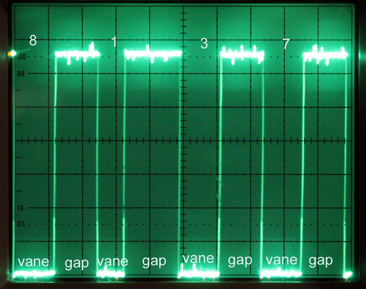
Low signal is the vane blocking the hall cell. High signals are gaps. Notice the long gap after 1.
The measured timing of the trace above is:
| RPM | Time for one turn | Perfect time between sparks | Time range between start lows | 8 vane | 8 gap | 1 vane | 1 gap | 3 vane | 3 gap | 7 vane | 7 gap |
| 585 | 204.8 mS | 25.64 mS | 25.4-25.9 mS | 12.7 mS | 12.3 mS | 8.5 mS | 16.7 mS | 12.6 mS | 12.3 mS | 12.4 mS | 12.4 mS |
The entire timing relationship is between Hall cell position in relationship to the shutter wheel position. Timing has nothing to do with the stabbed distributor tooth, or the distributor housing to block position. As long as you can rotate the housing to align the tailing edge of the narrow tooth to the Hall sensor trigger point, timing will be correct. Taking the distributor out and moving it one tooth will only change the required final housing position, it will not change anything else. Re-stabbing will not change rotor phase, it will not change timing. Changing the stabbed position only moves the distributor housing position where proper timing occurs.
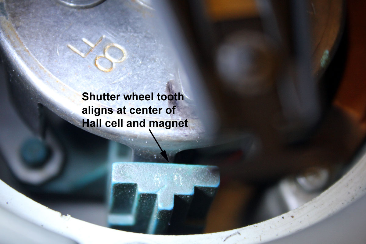
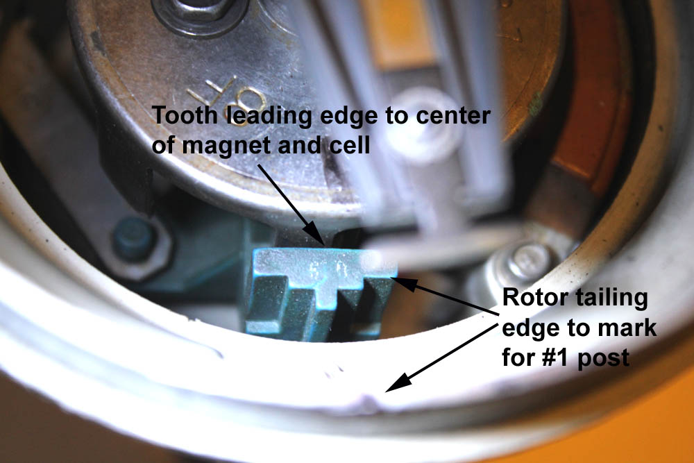
If you want to stab properly, put the engine about 10* BTDC, the distributor housing in a good position for adjustment rotation, and the leading edge of the shutter wheel number 1 tooth in the center of the hall cell gap. This will also point the trailing portion of the rotor contact blade at post number 1 inside the distributor cap.
The Hall cell gets power through, and returns PIP signal through, these three terminals:
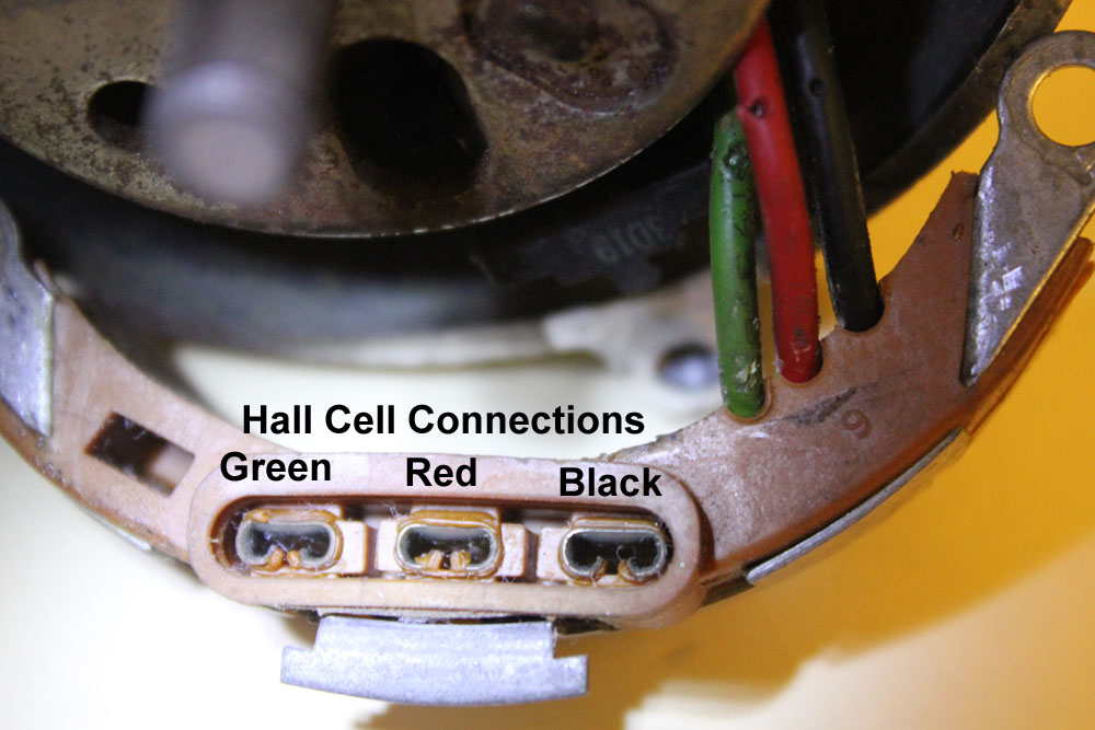
Make sure these female terminals are clean, and give them a light coating of dielectric grease.
The cell wires pass right through to the terminals. For maximum life and reliability, push a small amount of Permatex 100% pure silicone dielectric tune-up compound into the terminals. Don't listen to anyone who tells you dielectric compound will insulate the terminals!!
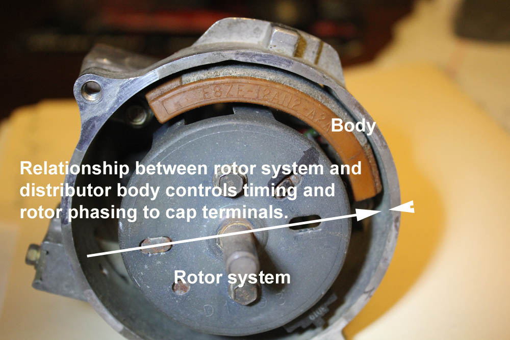
Timing is set by the relationship of the distributor housing to the shutter wheel:
Contrary to rumors, the stab position is totally meaningless for distributor rotor to terminal synchronization or timing.
Stab Position and Initial Timing
The stab position only changes the position where the housing produces the correct timing.
If you can rotate the distributor housing to the required position for proper timing without bumping into anything, and if the wires reach, you can slap the distributor in at any position on any tooth you like. In the case this Ford TFI system, all you would have to do is make sure the rotor's knife edge contact is near the exiting side of number one cap terminal when the crankshaft is set at the desired initial timing on the compression cycle for number one.
A PROPER installation for a 5.0 HO with EEC IV would be:
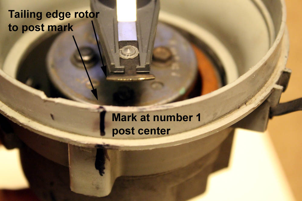
Shutter narrow tooth in gap by magnet when rotor trailing edge is at post 1
This is what you want with the distributor seated.
Anything done to the distributor externally, including the particular tooth stabbed, will not change rotor phasing, or the rotor tip position in relationship to the cap terminals when spark occurs. Rotor phasing, or the position of distributor rotor to cap terminal at spark, is controlled by shutter wheel-to-rotor relative position, the pickup position, and the position (clocking) of the cap on the distributor body. To change phasing, you have to relocate the rotor relative to mounting shaft and shutter wheel assembly, clock the hall cell with the vacuum advance lock (if the distributor allows this), or relocate the cap's clocking position on the distributor body. Moving (clocking) the cap is often easiest. Shortening the vacuum advance lock bar will make the spark fire with an earlier rotor position. You will have to retime the distributor if anything is altered.
When the housing is rotated in the block, the cap and pickup rotate together the same degrees. This changes the timing of cam to housing, which changes the timing. Rotating housing to block always changes timing, but does not change rotor to cap phasing.
When we pick a new tooth, it changes the shaft position relative to cam. This changes the timing of shaft to housing, which changes timing. Rotating housing position will move it right back, as long as it can rotate without obstructions. Picking a new tooth cannot change rotor phasing or anything else. A new tooth simply requires a new housing position to produce the exact same results. The tooth stabbed simply determines housing position for optimum timing.
| Change this position | relative to | affects Timing | Rotor Phase | Housing Position (for same timing) |
| Housing | block | X | ||
| Gear tooth stabbed | cam | X | X | |
| Rotor clocking | shaft | X | ||
| Cap clocking | housing | X | ||
| Pickup clocking | housing | X | X | X |
| Shutter clocking | shaft | X | X | X |
Note: A crank trigger system mechanically separates the trigger point for the spark distribution. The spark timing is from a crankshaft reference, while the distribution is from the cam. Because spark trigger reference is mechanically independent of spark distribution, rotor phase will vary with either distributor rotation (rotor and cap relationship) or anything that affects timing (such as crank sensor position).
Be sure rotor phase is visually checked to center the rotor on the correct cap pin when mid range on timing. If the operating timing range is between ten degrees and 38 degrees, set the crank to 24 degrees BTDC on number 1 and center the rotor on terminal post 1 visually. This will make the rotor have a maximum error of 14 degrees as timing varies between 10 degrees and 38 degrees. If you make an error or have uncertainty, try to make the error in favor of the maximum advance setting aligning.
The distributor has the following rules:
This is how distributors with pickups inside work. The rules above include optical, breaker points, and magnetic effect systems.