FT1000MK_V
|
FT1000MK_V |
|
It's great to see a manufacturer offer improved close-spaced SSB transmit performance! The MK V Yaesu reverses other modern radio's downward spiral of transmitter SSB IM performance. Yaesu included a class-A mode. Even without class A, the HV finals can be very clean when compared to other radios if the rig is kept out of ALC. Unfortunately Yaesu missed correcting two important flaws:
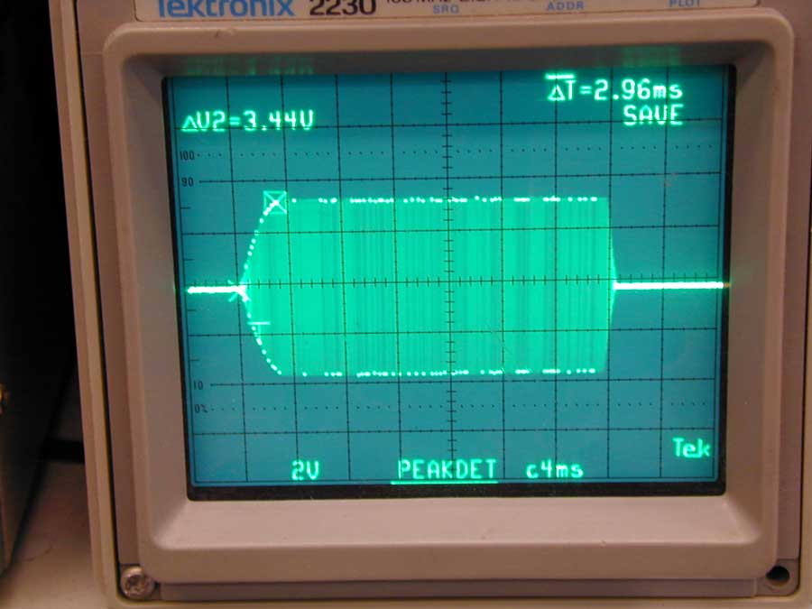
Preliminary tests show very strong keyclicks +1kHz and -1kHz. An early FT1000MK V tested here had 1mS rise and 2ms fall times with sharp edges. Later FT1000MK V's, are slightly better on and look like this:
The very sharp falling edge is a particular problem in later FT1000MK V's.
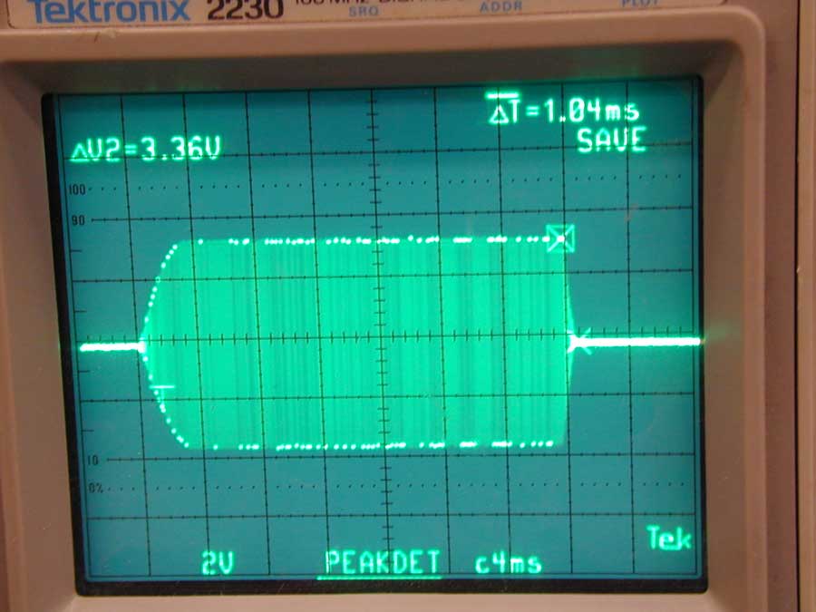
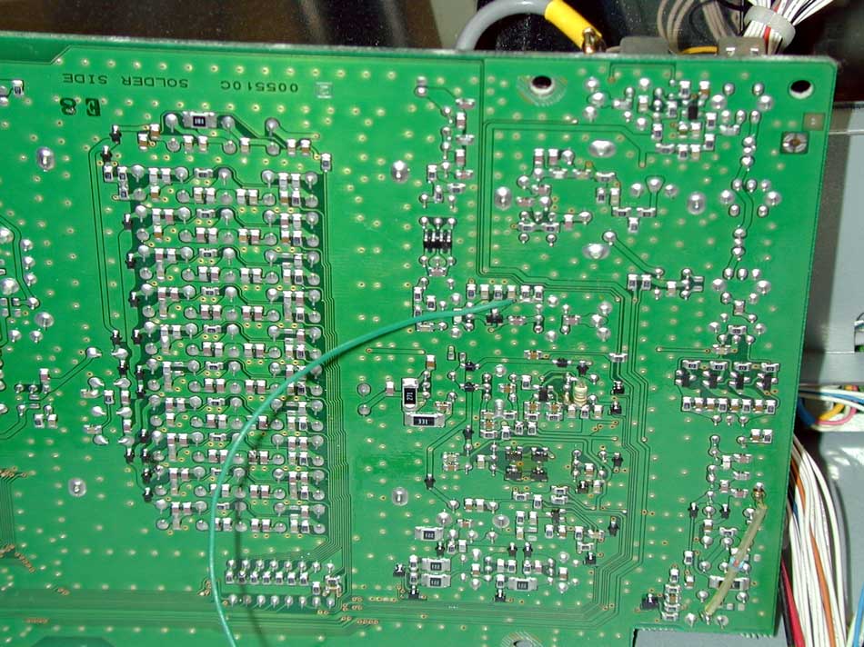
What does a 1mS fall mean?A CW signal is actually a 100% AM modulated signal. The fall (or rise) time makes up 1/2 the time required for a full rise and fall cycle. If the time period of the fall is 1.04mS, the frequency of the modulation frequency is the reciprocal of the rise (or fall) time divided by 2. 1/.00105 = 952 952/2= 476 Hz. The lowest order sidebands possible at ANY keying speed are 476Hz away from the carrier, one above the carrier and one below the carrier. This means the narrowest possible bandwidth with a perfectly shaped raised sine wave envelope would be 952 Hz. Since the FT1000 MK V does not have a perfect raised sine waveform, the actual sidebands contain high levels of harmonics. This makes the bandwidth even wider. It is the really sharp turn-over on the edges that kills the bandwidth. Radios almost always have a different bandwidth on make and break. This is because envelope shape is different on rise and fall. A stock FT1000MK V from Europe sounds like this in the USA! Wav file link Keyclick and Noise Blanker Mod for FT1000MP MK VSince a portion of the keyclick mod requires accessing the same general area as the noise blanker, it would be prudent to fix the receiver and transmitter at the same time. This article offers a combined modification that patches both problems. The NB ProblemThe worse thing about the receiver in any of the FT1000 series radios (I'm sure this carries over to other Yaesu models ) is the noise blanker. The noise blanker, even when OFF, causes deterioration in the close-spaced IM performance of the FT1000MK V. 1.) All signals inside the wide roofing filter (70 MHz) BW of the MK V are applied to the IF input of the IF unit. 2.) They immediately go through a very good balanced mixer (Q2020 and Q2024 in push-pull). This mixer has very little distortion and very good strong signal handling. 3.) 70MHz signals are converted to 8.2MHz . 4.) The 8.2MHz signals reach the gate of Q2009 through C2043 (darkened line on schematic). This point precedes all narrow 8MHz IF filtering--allowing a rather wide swath of unwanted signals to reach the gate of Q2009 along with the desired signal. 5.) Q2009 is left operating even when the noise blanker is turned off and can have substantial gain depending on bias voltages at TP2001. Bias voltages at TP2001 can be varied by changing menu settings for NB gain, but even the lowest NB gain settings never fully turn off Q2009! 6.) Q2009 acts like a mixer, creating unwanted mixing products of desired and undesired signals. Accumulated level of all signals reaching the gate of Q2009 produce a large net voltage at the drain of Q2009. This voltage (and resulting net current) causes overload and distortion by driving Q2009 and 2010 into distortion. 7.) The unwanted distortion products feed right back down the same connection into the 8.2MHz IF.
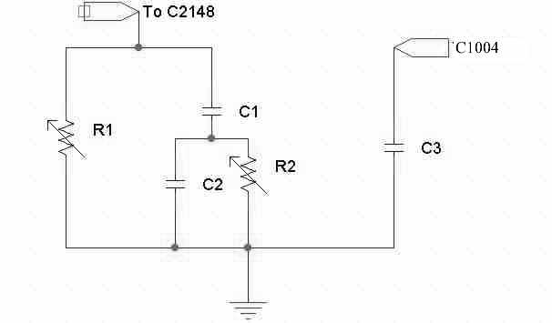
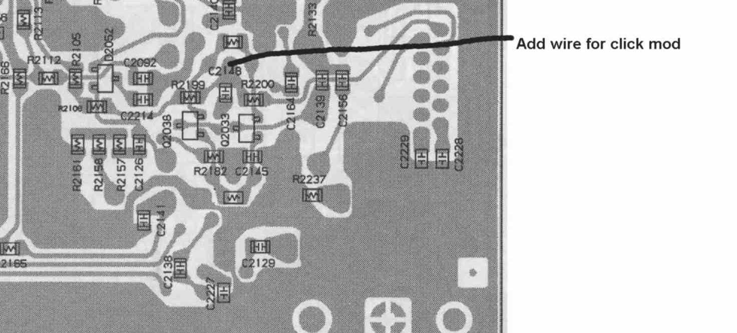
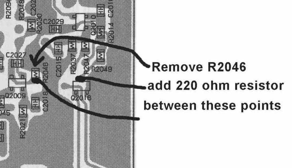
These new IM products appear as "phantom splatter" on SSB and " phantom CW signals" on CW. On CW, they sound like random blips and bloops that aren't real Morse characters. We cannot actually hear the distortion on the frequency of strong signals. The IM products simply appear as artificial interference when we attempt to copy weaker signals within about 5-10kHz of two or more moderately strong signals. Anything we do to increase IF or RF gain in front of this point will greatly increase unwanted noise blanker intermodulation products. This includes increasing 70MHz IF system gain. The NB ModThe NB mod is a simple effective mod. It improves close-spaced IM3 dynamic range about 10dB on average. In rare cases I have seen as much as 20dB change! Moving just one foil trace, a very simple manufacturing change, would have made the MK V receiver noticeably better in close-spaced performance. Fortunately this mod is fairly easy for owners. The NB correction removes surface mount 220-ohm resistor (R2046) from the source of Q2009, replacing it with a 220 ohm leaded resistor connected between Q2009's source at C2027 and Q2016's (2SC4047) collector and the junction of R2049 (also a 220-ohm). Keyclick ProblemRaised- sine rises and falls would provide the fastest possible CW speeds for a given bandwidth. With properly filtered rise and falls, we would hear little or no change or softness when listening on-frequency. Tuning off- frequency, clicks would quickly vanish. If a 2 or 3 millisecond rise and fall is used for operation at very high CW speeds in a single-pole R/C filter (this radio uses a simple RC filter) a transmitter is almost guaranteed to interfere with less strong signals within 1kHz or so. Transmitters with fast rise and fall times should stay at least 1.5kHz away from operators working weak signals, especially when the CW transmitter has 1930-era transmitter CW shaping. Rumors sine-shaped waveforms impact tone or readability of signals are false. Some people even claim clicks rolling off at some "X-dB-per-octave rate" beyond a few hundred Hz are a necessary part of life. Such statements are misleading, likely being based on the incorrect assumption the receiver has very wide bandwidth and the transmitter is filtered through a single stage simple resistor-capacitor click filter. If you want to hear the sound of proper shaping, listen to this click-free signal recording as I tune across the signal. Off- frequency (even a few hundred hertz), we hear no clicks at all. On- frequency the CW is "hard" sounding, allowing copy to 60-WPM or more. When the tone disappears in the deeper receive filter's skirts, clicks also disappear. In contrast, compare the MK V recording as I tune past the signal. This signal is from Europe on 40 meters! There is a day-and-night difference off frequency between the no-click and loud-click signals. On-frequency both signals sound the same. MK V clicks are caused by excessively fast rise and fall, and very poor shape of the rise and fall. Unfortunately when we patch poor CW transmitter designs, we can not make perfect corrections. Without major modification we can not modulate the MK V ( or most other transceivers) with properly filtered (which also means perfectly shaped) rise and falls. This modification, like the MP and 1000D click mods, is a patch...not a perfect cure...but it is about 20dB better 1kHz away than doing nothing about the problem. Patches Vs CuresBecause mods on existing radios are patches, the radio owner must make a choice. If the user operates speeds faster than 45 or 50 WPM, the rise and fall required for legal close- spaced operation may be less than ideal. This does not mean the ability to work weak signals at modest speeds (up to 30 WPM) would be compromised even the slightest amount. It means high- speed ops (speeds over 45-50 WPM) may find the CW slightly mushy when adequate for close-frequency operation. Operators with stock MP MK V's should always try to operate at least 4kHz away from weak or moderate signal- level stations. Part 97 rules prohibiting keyclick emissions that interfere with adjacent frequency operations. The specific rule is 97.307(b) "Emissions outside the necessary bandwidth must not cause splatter or keyclick interference to operations on adjacent frequencies." The Click ModThe actual click mod requires changing two stages. The first stage modified is on the IF board. The IF mod slows the rise and fall of mixer transistors Q2033 and Q2038. Note: This stage is easy to modify, and is located on the same board as the noise blanker. This allows the noise blanker to be corrected at the same time.By itself, modification of the easy-to-reach IF board is NOT effective for substantially reducing clicks. A later stage on the RF board also has truncated rise-and-fall times with a very poor R/C edge-shaping system. This later stage continues to add clicks even after earlier stages are modified. RF amplifier stage Q1001 has the fastest rise and fall in the RF section. Q1001 must have proper gate bias shaping and timing to reduce clicks to acceptable levels. Removing D1002 and altering components around Q1002 slightly reduced clicking, but I concluded any effort wasn't worth the result with bias rise and fall more rounded at Q1002. As designed, Yaesu uses a square wave very rich in harmonics to drive a simple R/C filter. This poorly filtered square wave amplitude modulates the RF and IF sections. The poor basic filtering design, combined with non-linear amplitude response, requires great care in component selection. It also means we never will achieve the optimum bandwidth for any give rise and fall time and ultimate CW speed. Making the ModThis mod is a little more complex than the FT1000MP mod because the chassis of the MK V is a little more complex and unfriendly. Like any service work, having a clean open bench and a spot to separately store screws and other hardware removed in every step in order will make the job smooth and easy. If you do NOT want to modify your MK V, I can make the modification for a nominal fee. You can e-mail me at my callsign@mycallsign.com Some may wish to remove and change surface mount components... but I prefer to wire the click-mod to a single terminal strip. This will allow you to customize the mod, switch the mod in and out, or correct any errors without dismantling the entire radio. You'll need the following parts: (1) one foot each of two small insulated wires, #20-#26 one ( preferably) green and one blue to make connections (1) four-lug (with ground) terminal strip (3) .1uF 50 volt disc capacitors (C1-C3) (1) 22k 1/8w fixed resistor (R2) (1) 680k 1/8w fixed resistor (R1) (1) 220-ohm 1/8w fixed resistor In addition you need a well-lit bench, along with some hand-tools such as soldering pencil and solder, screwdrivers, and cutters and strippers. Populate the terminal strip as follows:
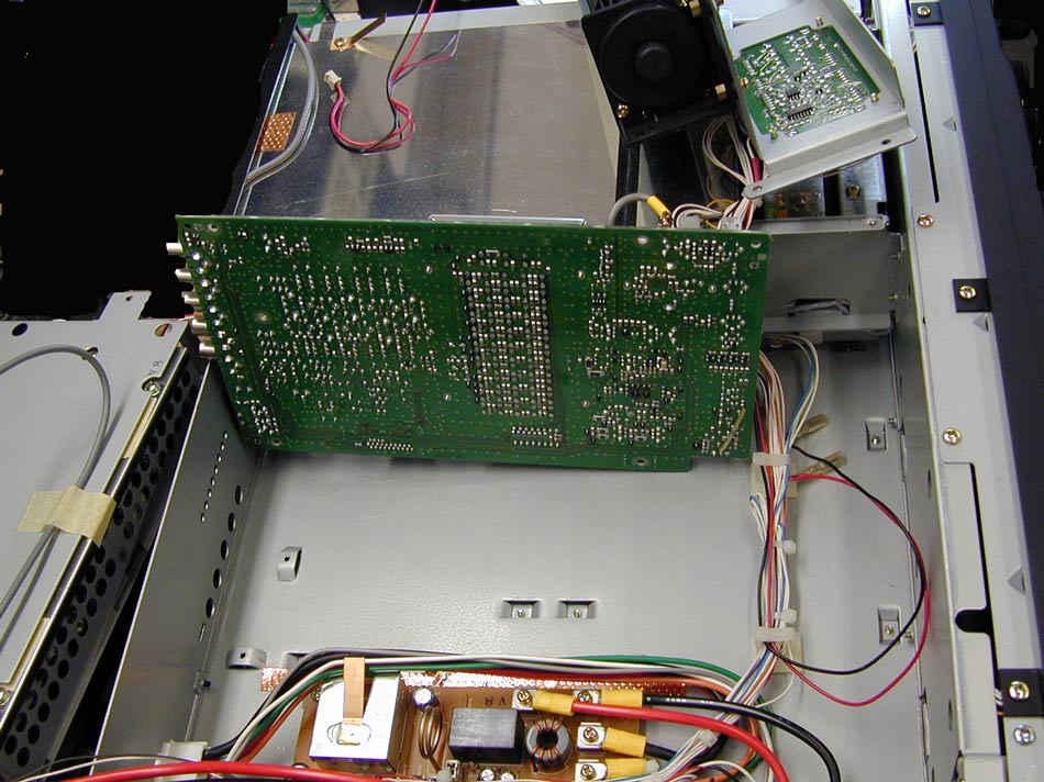
IF Board ModsClicks1.) Remove top and bottom covers to gain access to internal circuitry. 2.) Remove the screws holding the IF board in place, and the minimal amount of plugs to allow flipping the IF board over. You should be able to flip the board over by removing only two ribbon cables and one shielded cable. Draw a roadmap of all plugs and cables that must be disconnected! This will help you remember where everything goes.
(click here to download expanded IF board if needed) Click IF Board
Noise Blanker
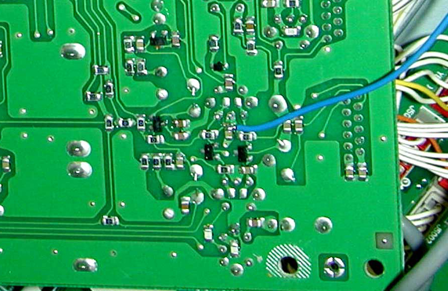
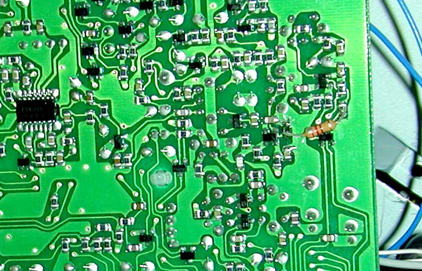
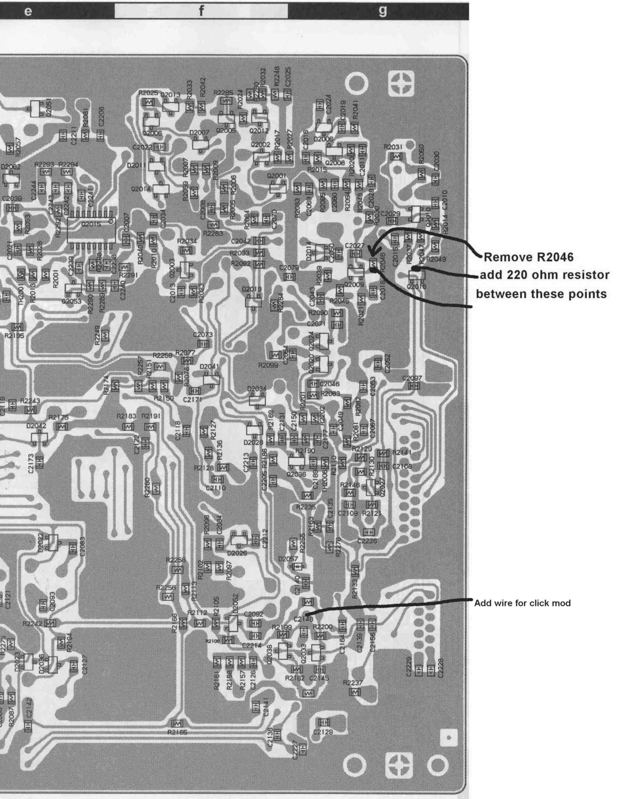
1.) Locate and remove R2046 220 ohm surface mount. 2.) Form the leads properly and solder a 220-ohm 1/8-watt leaded resistor to the Q2009/C2027 source and capacitor connection point 3.) Connect the other lead of this resistor to the junction of Q2016's collector and R2048. 4.) Reinstall the IF board with the flying lead exiting the closest edge of the PC board. The blue wire should just hang out the closest edge. Take care to avoid pinching any wires.
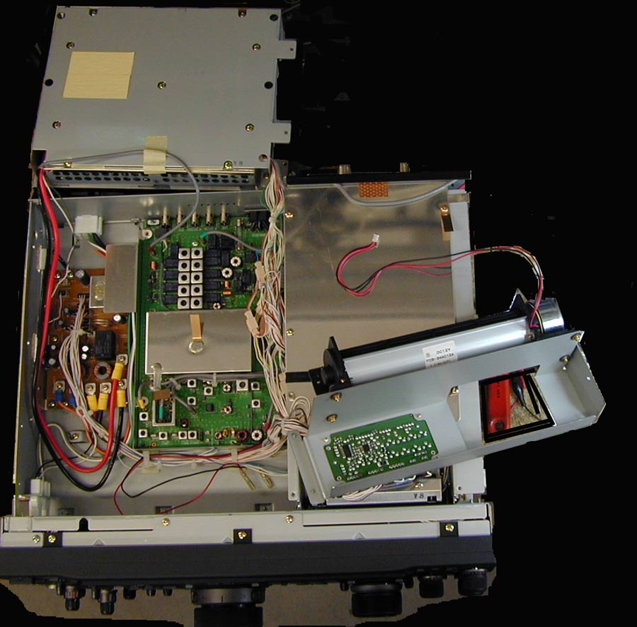
RF Board Mods (improves clicks only) 1.) Remove all hardware necessary to access the RF board. This includes the PA section and fan, both of which can flip over the case edge if a few wires are unplugged..
2.) Remove the RF board. You will have to remove a small shield panel and unplug some wiring. Be sure to remove ALL necessary screws, including black screws near the DIN jack on the back panel of the radio!
(Click here to download an expanded view of RF board if needed)
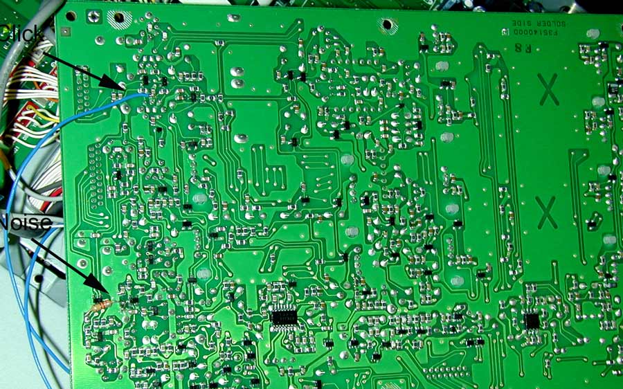
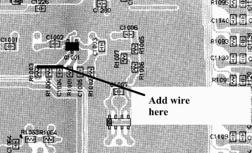
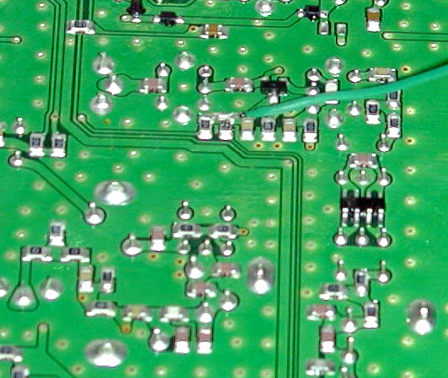
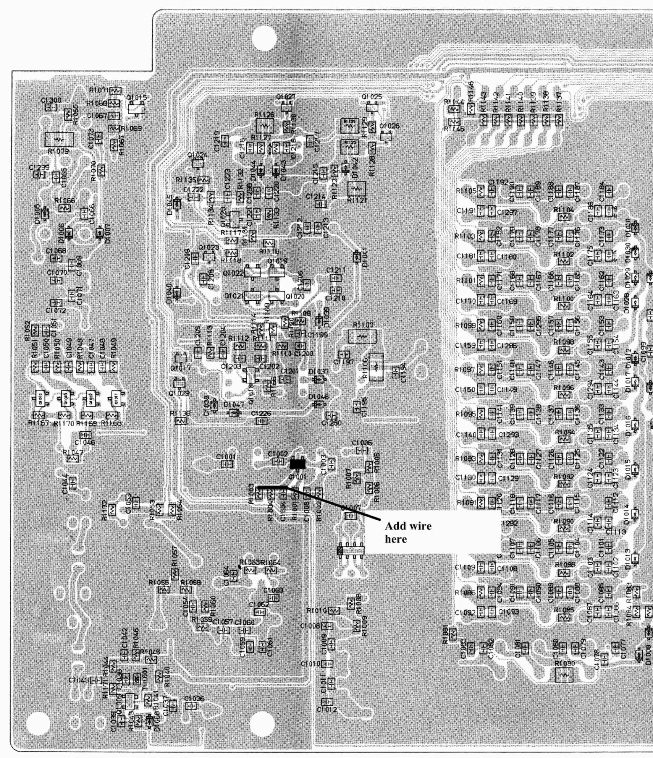
3.) Attach the green wire to the junction of C1004 and R1003/R1004 at the gate of Q1001. 4.) Route this wire up through any opening near the middle of the radio to an area near the IF board. 5.) Reinstall the RF board and all other hardware taking care to not pinch any wires, and to reconnect all unplugged wires in proper locations.
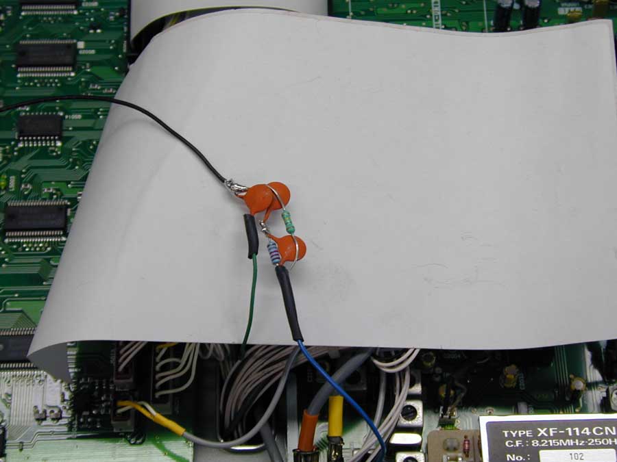
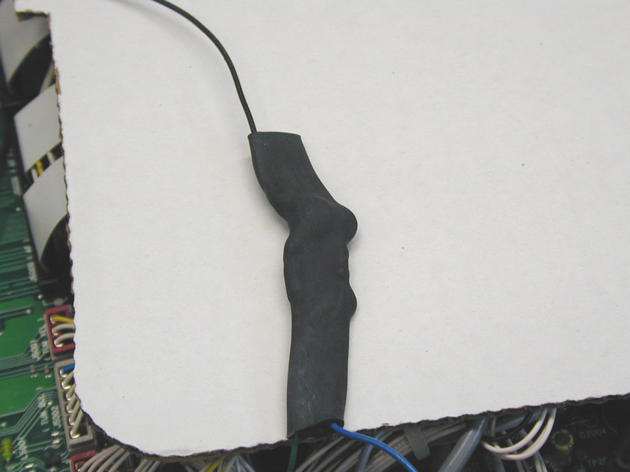
6.) Select a clear area on the IF board and mount the terminal strip under a convenient clear mounting screw area. (Note: I have simply heat shrunk the resistor capacitor network without using a terminal strip.) 7.) Connect the green wire (from RF board) to C3, and the blue wire from IF board to the junction of C1 and R1. R1 is a 680k resistor, and R2 is a 22k resistor(Example of heat shrunk construction below)
Reassemble, test the radio, and reinstall the covers. Transmit Gain MenusThe FT-1000 MK V has hidden transmit gain menus. They are accessed by pushing and holding FAST and LOCK while turning the POWER switch on. Both of my MK V's and every MK V serviced here has had the TX IF gain set too high. This causes first character clicks on CW and spits and splatter on SSB. Here is how to correct the IF gain to prevent ALC clipping on leading edges of CW and voice: Press and hold FAST and LOCK before and during initial POWER on. Press FAST and ENT at the same time. You are now in the MENU's and the display should say "0-1 GrPI-cH". Turn the VRF/MEM CH counter-clockwise to 9-2. The display should say "t iF - GA in" This is the transmit IF gain menu. Turn the SUB VFO knob clockwise one position to " t iF - 018". This is the 1.8MHz transmit IF gain. Press the ALC/COMP meter selector until the bar graph says "ALC". Set RF PWR knob to full power. With the radio on CW and a 50 ohm dummy load connected, close the key and adjust the MAIN VFO-A knob until the ALC display is about 75-85% of full scale on the illuminated bar marked "ALC". Press the next band button (3.5), make sure the radio is still on CW, and turn the SUB VFO-B knob clockwise one band to "t iF - 035". Again adjust MAIN VFO-A until ALC is at 75-85% of full scale. Repeat this process through all bands. Most radios I have tested require a setting of 2 to 4 on TX IF gain, with 3 being the most common setting. This change will reduce SSB bandwidth and distortion. It will also reduce keyclicks and annoying thumps on the leading edge of each Morse character.
Copyright W8JI 2004. No portion of this page can be copied or reused without permission.
|