Related page: Screen Supplies
This page explains how to calculate resistors for a grid-driven class AB1 amplifier. These are all class AB1 amplifiers, with grids never going positive.

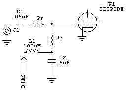
C1 is a low RF impedance capacitor, roughly 2 ohms reactance or less on the lowest frequency.
C2 is a very low RF impedance capacitor, roughly Rg/25 at the lowest frequency. Must have a very low impedance all the way to VHF!
L1 is a small RF choke with a few hundred ohms impedance at the lowest frequency. It might be a good idea to place a small resistance across L1.
Rg is the grid swamping resistor
Rs is the series resistor. This resistor might not always be used. If Rg is higher than 50 ohms, you will have to use a step up transformer or L network to match the grid. If RG is 50 ohms or higher, Rs is omitted.

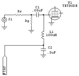
Alternate circuit. Not generally as stable as the first circuit because the choke is added. L1 should be shunted with a 2k-5k resistor.
C1 must present a low impedance all the way to VHF.
(Please give me credit for this if you use it.)
The following formulas apply to class AB1 amplifiers.
Where:
Eb = bias voltage
Pd = drive power in maximum PEP
Ipk = peak current in grid resistor
Eb² / 2Pd = Rg
For cases where grid resistance is less than 50 ohms, use the following:
The first step finds the peak resistor current in a 50 ohm load.....
(√ of Pd/50) * 1.41421356 = Ipk
The next step finds the grid resistor value....
Eb/Ipk = Rg
The final step finds the series resistance....
50-Rg = Rs
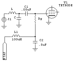
For cases where grid resistance calculates to be over 50 ohms, use the following:

L and C are an L network. Otherwise you might be able to use a broadband transformer.
Where:
Eb = bias voltage
Pd = drive power in maximum PEP
Ipk = peak current in grid resistor
Eb² / 2Pd = Rg
Examples:
| A 4CX5000 has 300
volts of grid bias,
and you have a
~100W PEP exciter.
Eb=300 Pd=80 (to
have headroom for
variables).
Eb² / 2Pd = Rg so 300^2/ 160 = 562 ohms for Rg.
|
next case:
| We have a grid driven 6146B amplifier with -45 volts of control grid
voltage and 2 watts PEP drive from a 12BY7A driver tube. Eb=45 Pd=2 Eb² / 2Pd = Rg so 45^2 / 2 = 506 ohms This means the grid impedance would be about 500 ohms. The 12BY7 would have to match that impedance.
|
Another case:
|
A tetrode has
35 volts of bias and
we have 100 watts
PEP minimum drive at 50 ohms. (√ of Pd/50) * 1.41421356 = Ipk sqr (100/50) * 1.414 = 2 amps peak current into 50 ohms next: Eb/Ipk = Rg = 35/2 = 17.5 ohms grid 50 - 17.5 = 32.5 ohms for Rs The exciter sees 17.5 + 32.5 = 50 ohms. With 100 watts current is 1.414 amps RMS or 2 amps peak, so peak grid voltage is 2*17.5=35 volts. This swings the grid from -70 volts down to zero volts, the grid never goes positive.
|

Also see Neutralizing Amplifiers