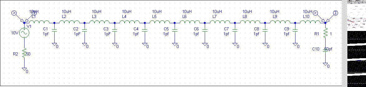
Spice model of inductor including stray capacitances:
Simulation.
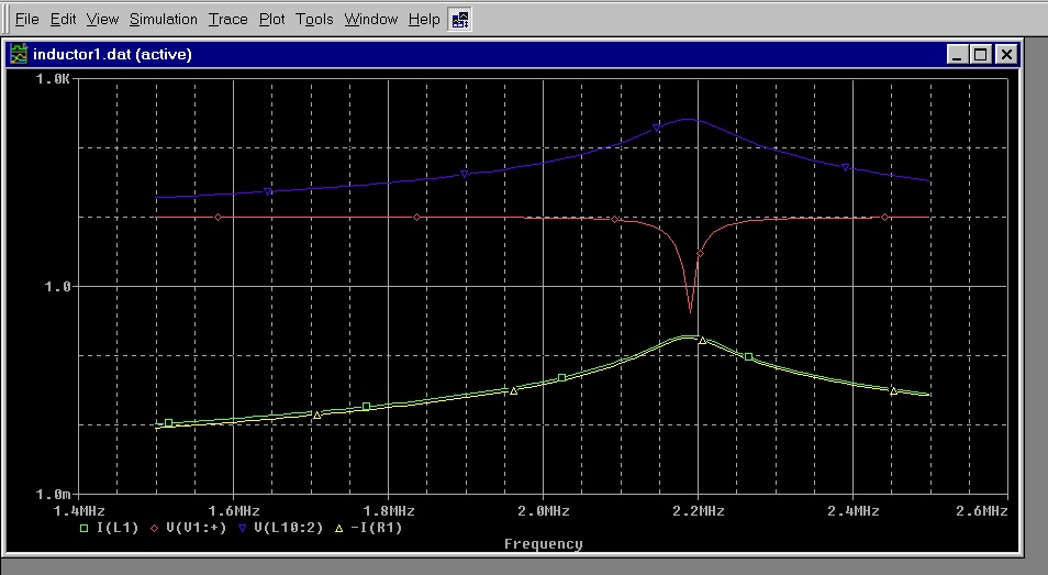
Red=input voltage
Green=input current
Blue=load voltage
Yellow=load current
This system (including reasonable leakage capacitance) representing a 50 ohm source driving a 100uH inductor with stray capacitance of 9pF and a 50pF load (small whip), shows input and output currents are essentially equal, while output voltage greatly increases at resonance.
In the following SPICE plot, increasing stray capacitance shows expected departure from equal input and output currents. Distributed capacitance to ground is now at 45pF, nearly equal to the 50pF antenna capacitance:
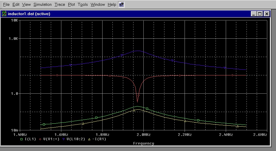
Again despite stray capacitance nearly equaling load capacitance, current levels at input and output are reasonably similar:
Green=source current
Yellow=load current
Red=source voltage
Blue=load voltage
If we multiply output voltage times current, the apparent power is many dozens of times the input power. The reason is simple, phase relationship between voltage and current along the inductor changes even while current remains essentially uniform.
Although casual experimenters often assume a loading coil "replaces" the missing length in an antenna and has sinking voltage with rising current, this is not the case unless stray capacitance is extreme or the inductor is incorrectly and inefficiently operated at or near self-(series) resonance. The loading inductor really just corrects power factor, and bringing voltage and current into phase at resonance. It does replace missing length by simulating an antenna.
Linear loading is no different, it simply behaves like a very lossy low-Q coil and does not add radiation to the system. Unless of course we are talking about heat radiation.