Curing FT 1000 MP CLICKS
FT-1000MP Measurements
I measured two sample FT-1000MP's (an early and a late model) by operating them into a high power fixed 30 dB attenuator pad. The output of the 30 dB pad was connected through a 3-way splitter to a step attenuator and conventional receiver, a spectrum analyzer, and an oscilloscope. The receiver used a 300 Hz eight-pole filter, the spectrum analyzer used a 50 Hz filter, and the scope was triggered from an external keying signal. Power was measured on a conventional Bird average reading meter.
At 1kHz spacing clicks from the stock FT1000MP's were about 15 dB worse than clicks from my old test bench radio (a well-worn ICOM IC-751A) and more than 20dB worse than the clicks from my click-reduced FT-1000D!
Here is a spectrum display of my stock IC-751A using 30 Hz analyzer bandwidth and ten second sweep:
The 751A is approximately -58 dB at 1 kHz, and rolls off smoothly.
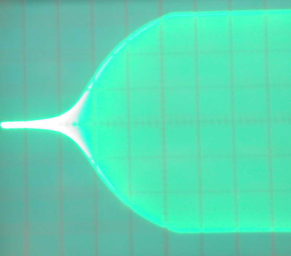
Here is the nicely sloped but too fast rise:
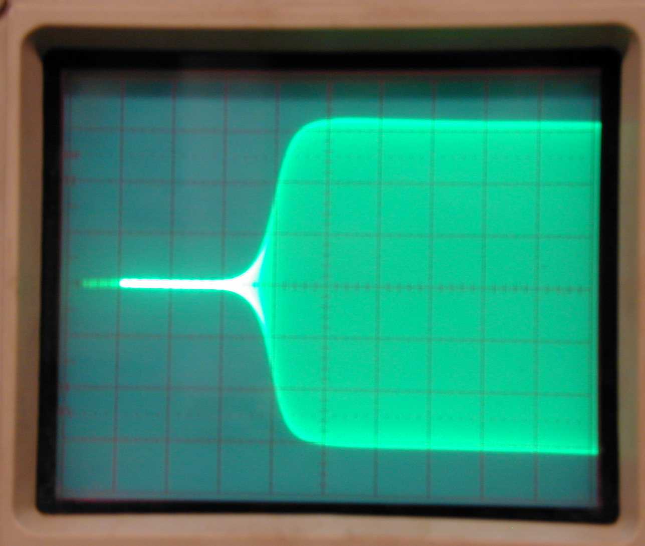
Rise approximately 3 mS....and the slightly sharper at the corner fall:
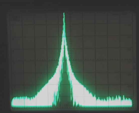
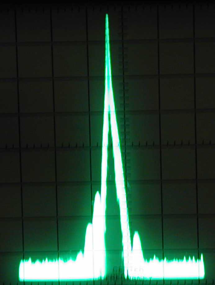
Now the stock 1000MP spectrum:
The FT1000-MP is approximately -50dB at 1kHz. It is 8 dB worse than the already "hard" 751A, and has a plateau below the carrier frequency that hovers around -55dB.
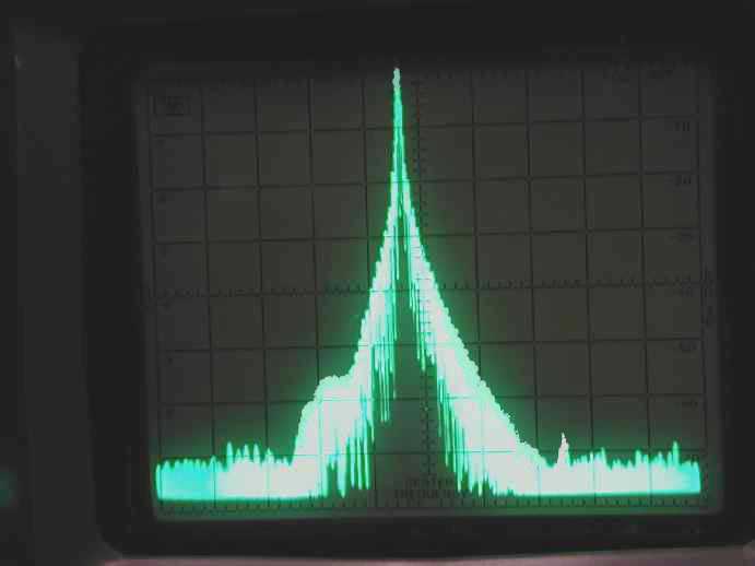
In direct comparison, here is a "de-clicked" FT-1000MP:
The modified FT-1000MP rivals any of the better radios I have tested, including my "de-clicked" FT-1000(D).
The modified FT-1000MP is around -85 dB at 1 kHz, over 30 dB improvement from the stock MP! Rise time is close to ARRL standards of 5mS, while fall time is around 3 mS. FT1000MP modified rise:
Rise 6 mS. The upper edge is a little sharp, but why worry....clicks are reduced 30dB or more!
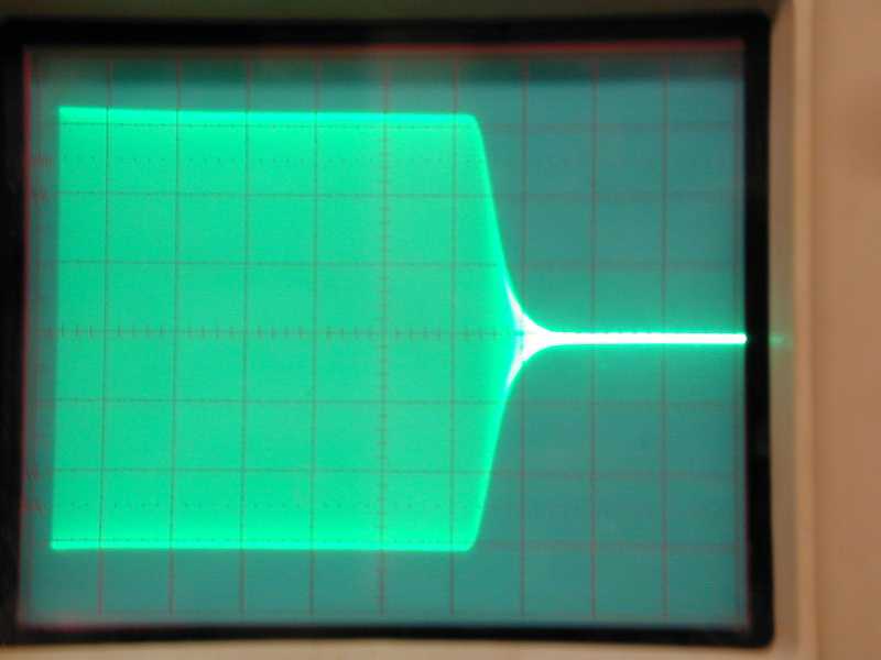
Modified MP fall:
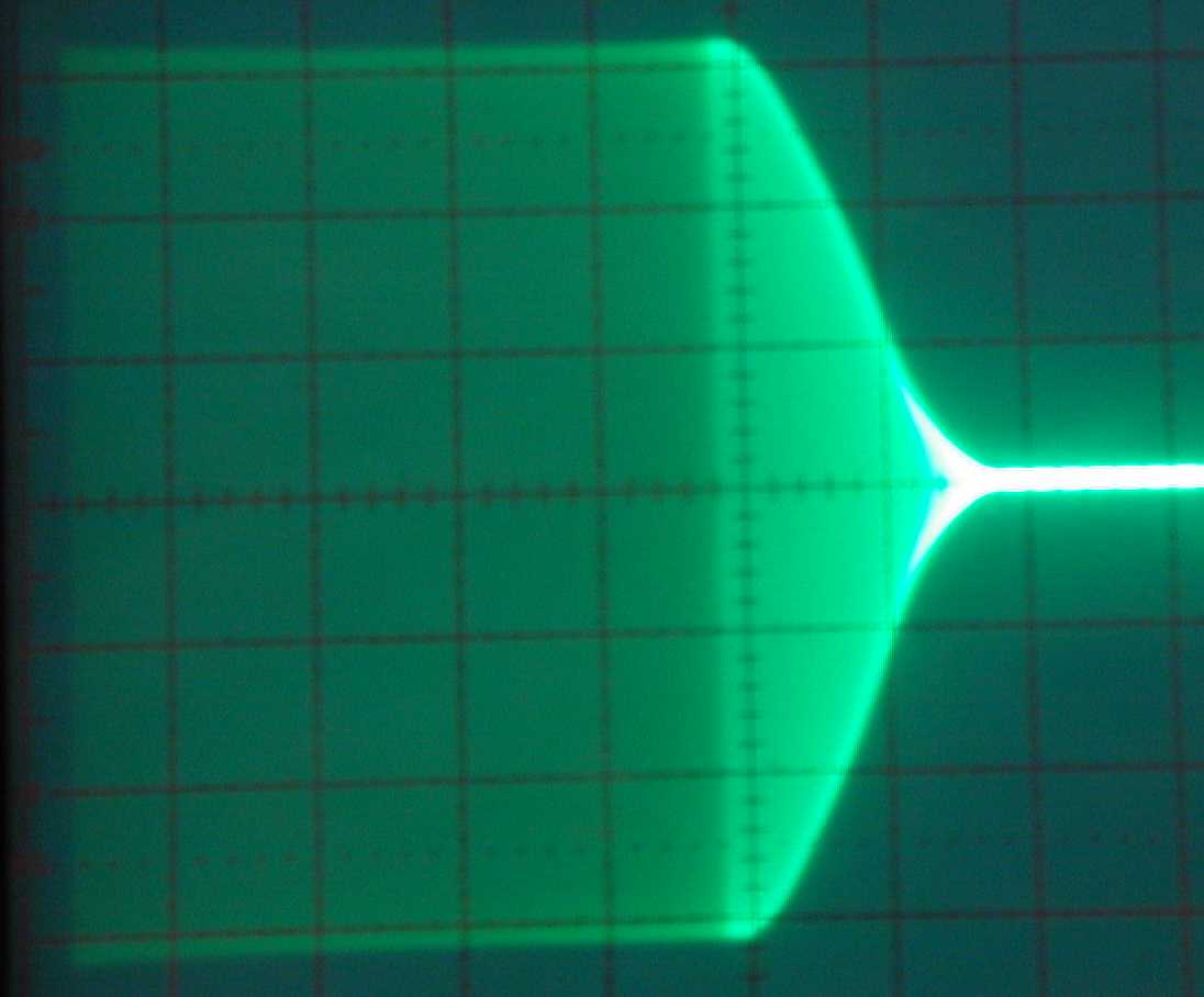
Fall time is around 3mS. While it has much more rounded edges, the slope is still not very "round". Unfortunately we are limited by what is possible to do, and this mod is already difficult enough for laymen.
Some concerned was expressed over the "power" of dots when using long rise and fall times. One simple solution is to turn up the weight control slightly. Keep in mind, even without ANY external weight adjustment, the change in average dot power at 45 WPM was only a few percent! On the air tests with VK3ZL and ZL3REX on 160 meters with fading signals and noise, revealed both could tell absolutely no difference between having the click filter in-line and out-of-line at 40 WPM CW speed. This waveform meets FCC and CCIR specifications for 60-WPM CW modest strength signals, and 35 WPM weak fading signals.
The best method of nulling clicks is by listening on another receiver with a narrow filter. Make sure you are well below overload on the receiver, and set that receiver so the carrier from the MP is just outside the passband of the test radio filter. It is almost impossible to use any other method for proper adjustment, including watching the envelope on an oscilloscope.
Work in a clear uncluttered location, I like to work with the radio on a clean small carpet on a well-lit bench, and have a container for all the hardware I remove.
Here's how to make connections to necessary points:
1.) Remove the top and bottom covers of the radio and set them aside.
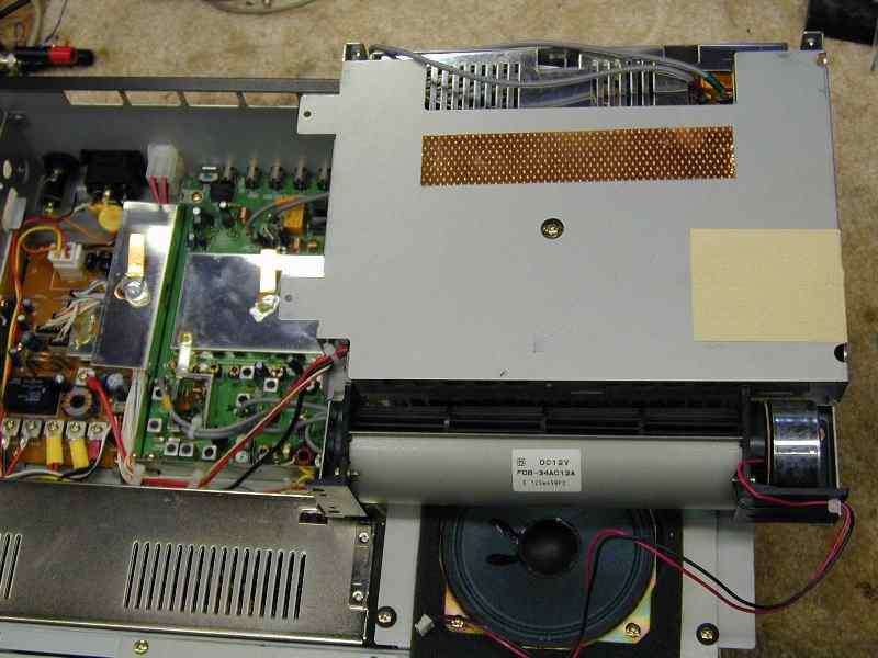
2.) Invert the radio, so you have the heatsink exposed.
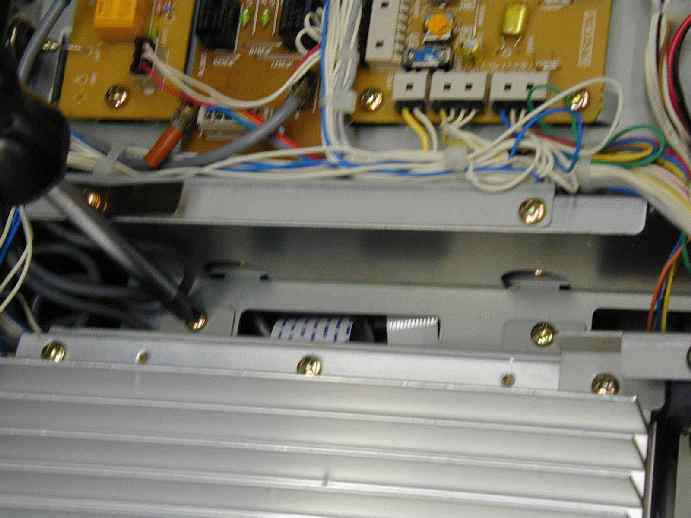
Four main screws hold the heatsink mounting bracket. Two are shown above (one under the screwdriver and one to the right of it). Two other screws are on the side of the radio chassis. You might want to remove the long screws holding the fan bracket, although I got by without doing so.
3.) Lay the fan and PA assembly out of the way, you may have to open some of the wire harness clips to get more wire. Unplug the fan so it is totally free from the unit. It should look like this now:
4.) The RF board is the green-colored board you see above. There are several screws holding that board down, and two screws on a rear panel DIN connector that is mounted on that board. The board will freely move when you remove ALL the screws. Do NOT pry or force the board out, if you have to pry you missed a screw!
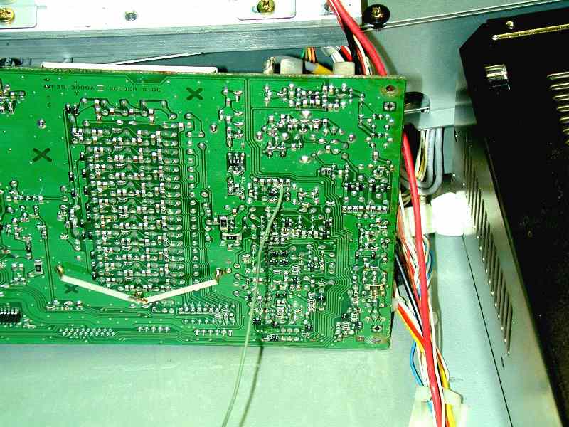
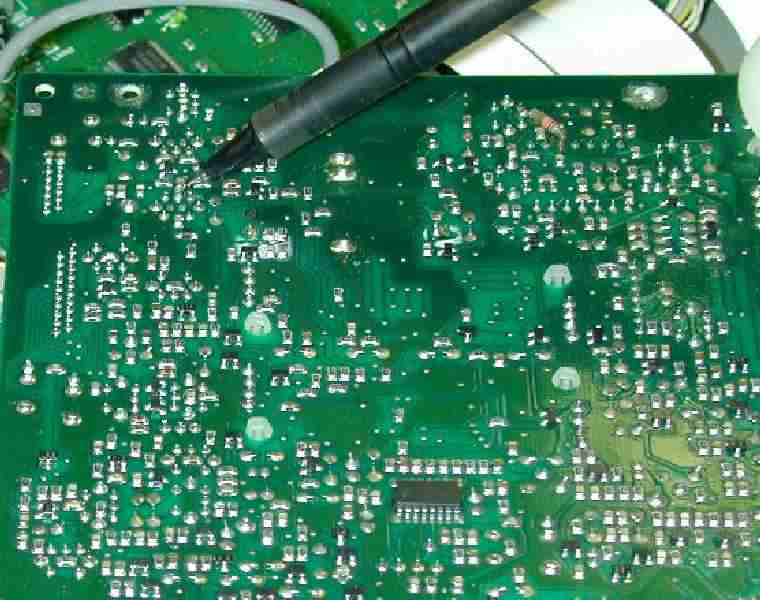
5.) Flip the board over, you might have to unplug a wire harness or two...but I managed to work without doing that. The board should look like this:
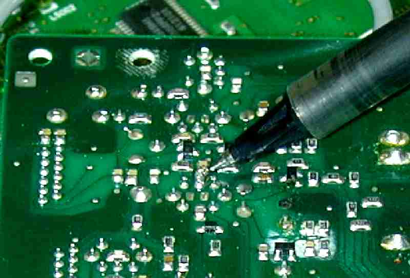
6.) I added the green wire you see above. I tacked it on a foil pad by laying the wire across the point where two chip components soldered in, as shown below:
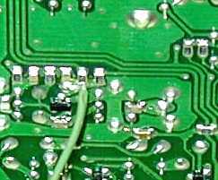
You can see the little black FET (Q1034) and the slightly triangle-shaped foil trace that connects to Q1034. I bent an "L" in the small wire I used. The wire will route topside to a terminal strip, so it needs to be several inches long.
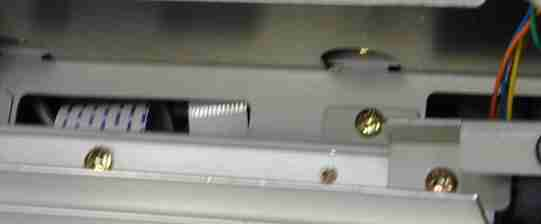
7.) The new wire routes under the RF board to an oval slot in the chassis, where if feeds to the other side and emerges near the IF section unit. Be careful not to pinch any wires when remounting the circuit board. The opening on the right is best for getting the added wire topside:
8.) While re-installing the RF section, fan, and heatsink inspect the wiring carefully. Be sure nothing is touching moving parts of the fan, and be sure no wires are pinched or left unplugged. It might be advisable to check the radio quickly on a dummy load to be sure the transmitter section works properly.
9.) Flip the radio over, and remove the two ribbon cables connecting to the IF section:
10.) Remove the mounting screws and flip the IF board exposing the bottom:
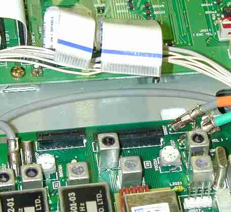
This is the area where the wire attaches to the IF board:
Note the FET above and to the left of the pen, and the IF transformer (two can shield connections and five electrical pin-outs, with an unused pad-set for a surface mount device in the center of the transformer leads) below the pen. The connection point for a new small insulated wire is the chip capacitor (C2148) pad that also connects to the center pin of the top three in-line pins of the IF transformer.
11.) Attach a small wire to the point mentioned above. It will route to the new circuitry.
12.) Re-install the board. Be sure you do not pinch any wires. Be sure you do not forget to plug in the ribbon cables, or any other wires you removed.
I mounted a small four lug (plus ground) terminal strip at the left front corner of this board, and mounted the components on that strip. This allows you the ability to change or adjust the mod if you find it too soft for high-speed operation.
Doing The Mod
The ideal CW radio would use a high-order filter with controlled group delay, and a reasonably linear attenuator or modulator to control the envelope shape. All other stages should be fully on just outside the output window of the CW signal. I initially hoped a CW "modulator" could be added on, but for now it appears modifying the 1000MP to ideal circuitry would be too involved. My only option was to "hunt and peck" and find a modification that would be reasonable to do, and inexpensive. This is the best solution I could find, reduction of clicks was excellent. The only drawback is two resistors need to be hand-selected, and the radio needs some minor disassembly to reach a connection point on the RF board.
I mounted this mod on a separate terminal strip under a screw on the left front corner of the IF board. This allowed me to experiment with component values while watching bandwidth and other parameters. This is the basic circuit I used:
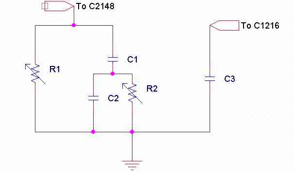
C3 was a .1uF disk capacitor. The value turned out to not be especially critical, it mainly seems to prevent rapid rise and fall of the low-level RF amplifier stage that is driven by a gate. There was no combination of resistance across or in series with this capacitor that reduced clicks in any of the radios I tested.
C1 and C2 are also .1uF disc capacitors. In all units tested, I could find no better combination for reducing clicks.
The only critical components appear to be R1 and R2. R1 ranged from 120k to 470k in the units I tested. R2 ranged from 1k to 10k ohms. I initially clipped in potentiometers, so I could listen to the output and adjust the clicks at 1kHz spacing. Both pots were adjusted for a null in click amplitude. That null is rather sharp, and turned out to be around 30 dB deep. This takes the 1000MP from being one of the "clickiest" radios I have found to one of the cleanest!