
Revised 1/31/04 at 0130Z
Receiver Improvement for FT-1000 and FT 1000 D
The
FT-1000(D) runs an essentially unshaped CW waveform into the filters. This harsh
signal generates unnecessary key clicks. The clicks are strongest from almost 1
kHz below to 2kHz above the transmit frequency.
The
cure:
I now have a plug-and-play 100% tested mod for the FT1000 and 1000D. This mod just plugs in, and includes the receiver NB mod.
Neither mod requires soldering! Only a screwdriver is required. The price for both mods is $53 Priority Mail in the USA. You can contact me at the following address
click this link to View FT-1000 and FT-1000D plug-in modification kit
Locate
the seven-pin connector J3024 at the middle-front of the AF board. (The AF board
is the one with the audio, PTT, ALC, and key jacks as well as other connectors.)
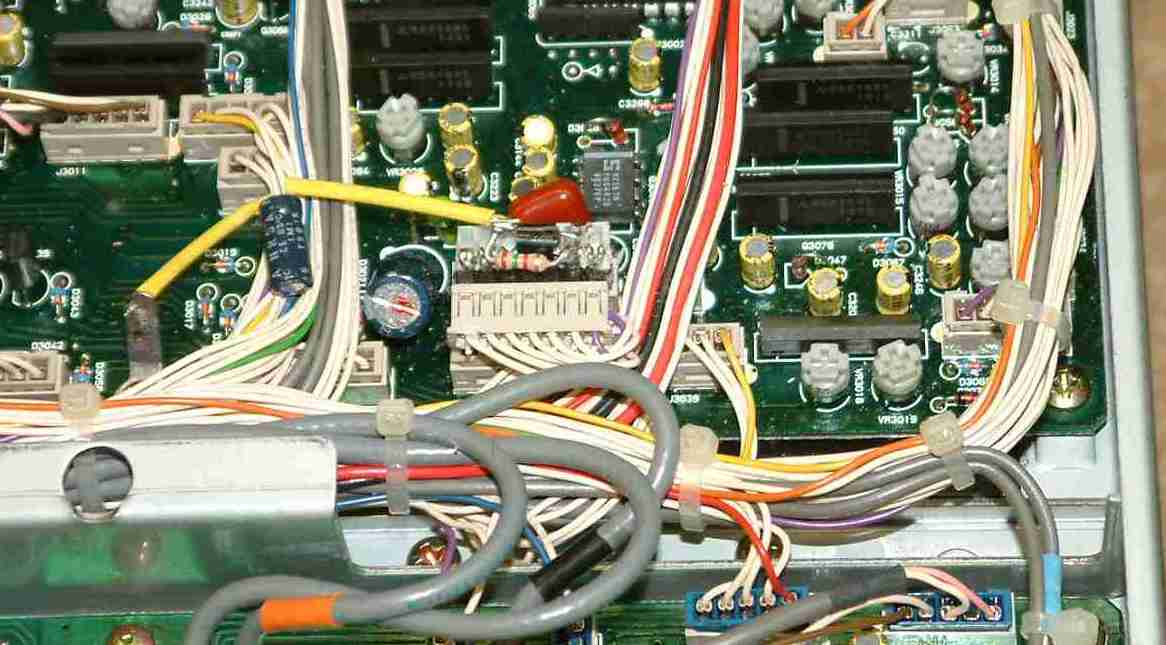
This is a picture with a hand-wired mod in place.
Cut
the wire going to pin 2 T CNTL). This is the second terminal from the right
(front of radio viewing). This is NOT the lead with 9 volts (nine volts is on
pin 6). If you are unsure you counted the correct direction, measure the voltage!
Connect
the collector of a 2N3904 to the flying harness wire you just cut.
Connect
the emitter towards the jack on the wire you just cut. This transistor MUST be a
2N3904.
Connect
a 1.5k resistor from collector-to-base on the transistor.
Connect
a 10uF, 25-50 volt capacitor from base to ground. A non-polarized capacitor may
be better if you can find one. No one has reported problems with normal
electrolytics as long as the positive lead connects to the base of the
transistor.
This
modification slows the waveform rise and fall times at Q3030 and D3009. The
result is a normally sloped CW waveshape into the SSB filter.
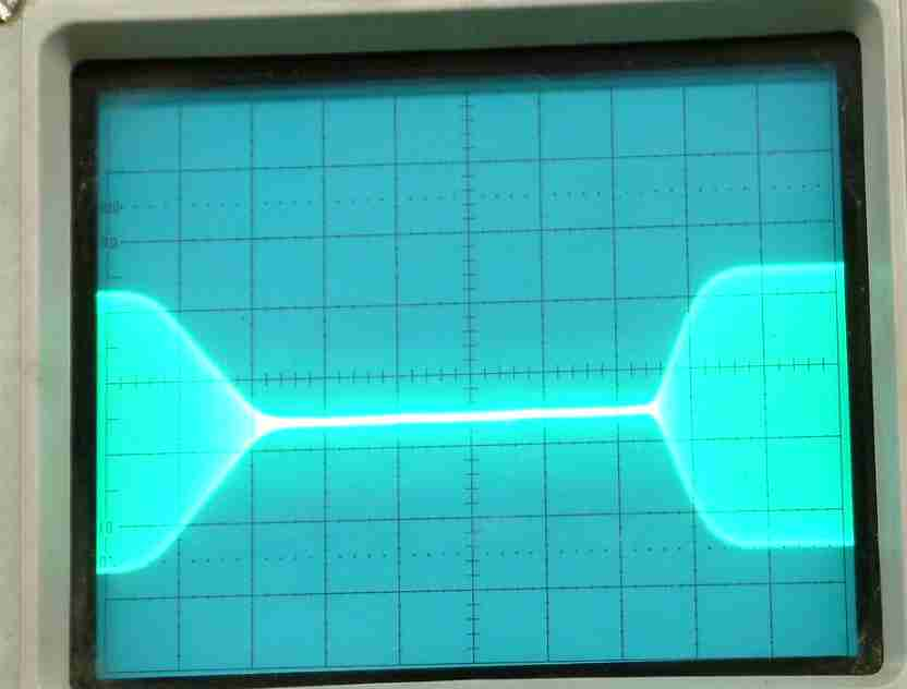
This is a nearly-perfect waveform with about 7mS fall and 4ms rise. The important thing is there are no sharp edges that cause clicks!
Clicks beyond 1 kHz above and below the transmitting frequency
move into the
composite transmitter noise, and there is about 50 dB reduction in clicks on
some radios
above the TX frequency!
Clicks
500Hz away are reduced about 20-35dB.
There
is almost no change in "keying sound" on the transmitting frequency.
The envelope shape is near ideal, and bandwidth reduction is dramatic.
Warning: This mod is NOT compatible with QSK with the full 10uF in circuit. For QSK use, I suggest adding a SPST switch from the 10uF capacitor to ground. You can place an additional 10uF capacitor across that switch, or simply add an additional 10uF in series with the ground lead from C1 ( this gives 5uF total value at the base of Q1) and not switch the system. When not operating QSK, I recommend using the full 10uF of C1 for the cleanest signal.
The ideal wave shape occurs when the ALC is at the upper area of the blue ALC line on the FT1000 meter. With full DRIVE, adjust for desired power with the RF PWR control. After achieving desired power, back the DRIVE down until the ALC indication just starts to move away from full blue area (half-scale). Anything from 1/3 to 1/2 scale is a normal waveform.
For lowest clicks, adjust DRIVE until ALC until it just registers (perhaps 1/8 to 1/4 scale on ALC).