W8JI House Hamshack
|
W8JI House Hamshack |
|
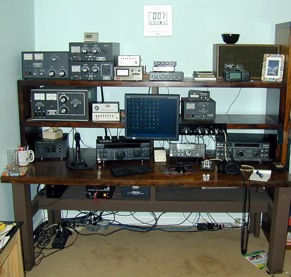
Related pages: Station Wiring (shows and describes wiring methods used) My station has come a long ways from the early 60's when I would drag old TV sets and radios home from the dump and take them apart to build my own receivers and transmitters. We were a very poor family and even had dirt floors in some rooms of our house. Ham radio became my life as I met many hundreds of very good friends all over the world. Some hams who stick in my mind as especially helpful and patient were: K8LRJ Junior Scott (Scotty) W8IQC Fred Mahaney W8JI, my current house operating position
Left to right top: AL800 six meter amp, ATR-30 tuners, rotating tower controls, audio controls, scanner
Left to right middle: AL-1500, TX antenna switches, monitor, keyer and ALS600
Left to right desktop: Six meter transverter, FT1000MP MKV, RX ant direction, Elecraft K3, FT-1000D
Lower shelf: Power supplies
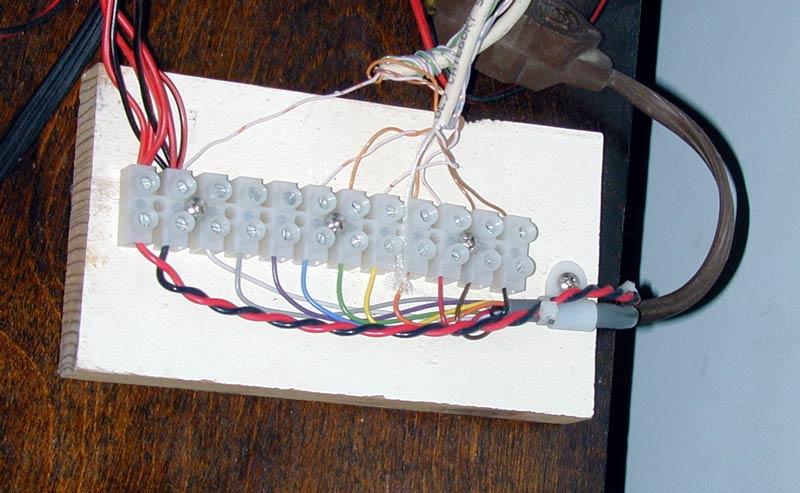
To reduce the number of wires running around, I have many little bench distribution feeds like these:
Each feed has 10-20 small control wires, 12 volts dc, and 120 volts in some cases. This allows me to wire rotors, 12 volt powered accessories, 120 v power accessories, antenna switches, and many other things to small easily movable blocks that just lay behind radios and accessories. 12 volt lines are fused with self-resetting 5-amp current limiting fuses at the main 13.8 Vdc power supplies. This eliminates dozens of wall warts. This feed runs my rotating tower antenna switches and my rotor controls for that tower, as well as an audio processor and scanner on the upper shelf. Notice I follow standard resistor color codes from black up through white.
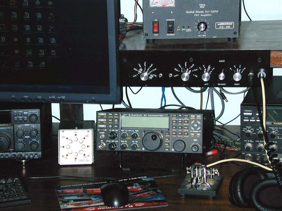
My receiving antennas and audio lines are selected by the switches below:
The left two knobs of this panel selects clusters of antennas. From left to right each of the two switches picks rear verticals, rear beverages, front beverages, front Europe beverage, rear Europe beverage, front Europe vertical, and a dipole located 3,000 feet away. It also selects my audio channels for left and right ears, and has my keyer and headphone jacks. The balance control feeds a mono amp for speaker use.
You can see a group of audio transformers between the little K3 and FT1000. These transformers prevent ground loop hums on audio lines.
I have seven basic receiving antenna systems, many of which I developed, popularized, improved, or optimized:
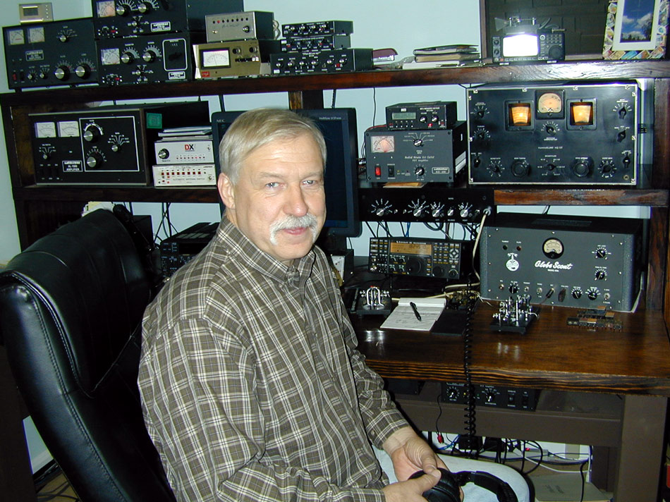
This is me January 1, 2010 during the Straight Key Night operation. This is a nice little rally for old radios and old manual keys. I forgot how much work and how much fun it is sending with a straight key! Boatanchor gear in use in this picture includes a Globe Scout 65A and a Hammarlund HQ-120. The HQ-120 includes the factory crystal filter. It was manufactured one month to the day before the WWII Pearl Harbor attack.
I have some old radios I occasionally like to use: My very first commercial rig from 1963 was a used Globe 65A and VF-1. Read more in Boatanchors Transmitting AntennasI have various wire and yagi antennas. Here are my main towers.
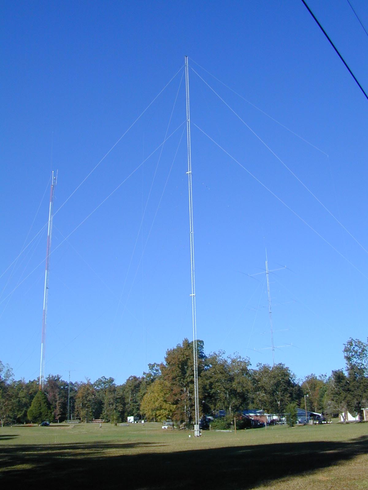
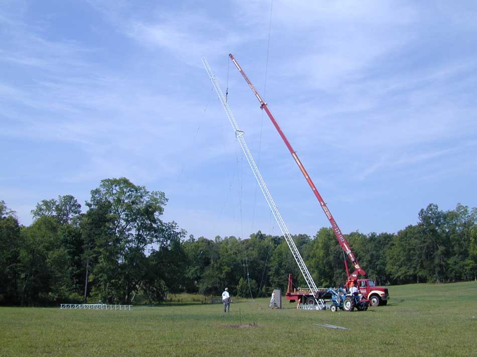
Left to right. 320-foot Rohn 65G, 70-foot Rohn 25G, ~200-foot Rohn 45G, 200-foot Rohn 55G that rotates.For a few details on my transmitting antennas see Transmitting AntennasLifting towers during installationLifting 45G for 160 meters:
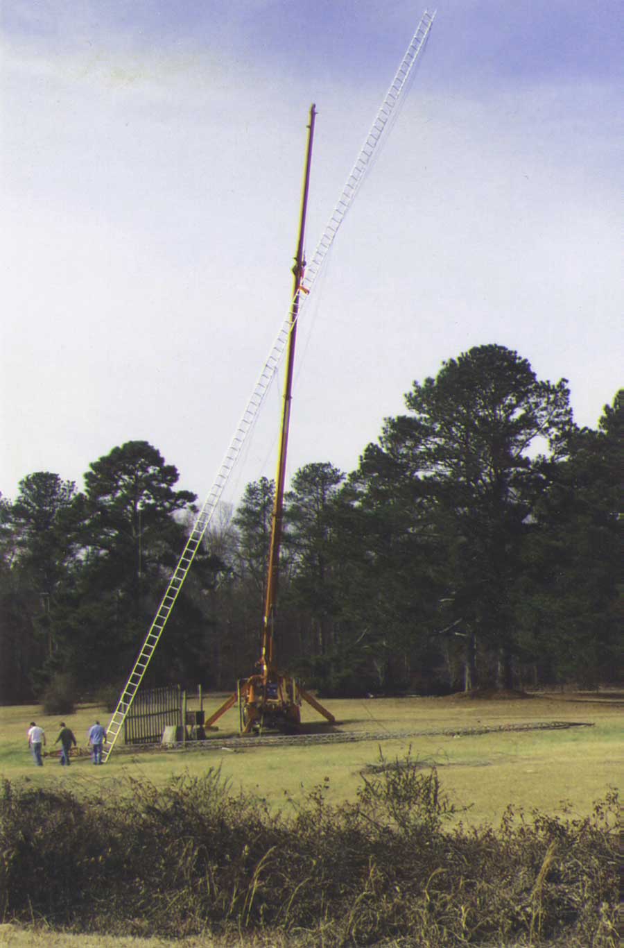
For more details on how we did this see Lifting Rohn 25G lifting 45G You can lift more than Rohn 45G. Here we are lifting the first 120 feet of a 200- foot tall American 19" face tower:
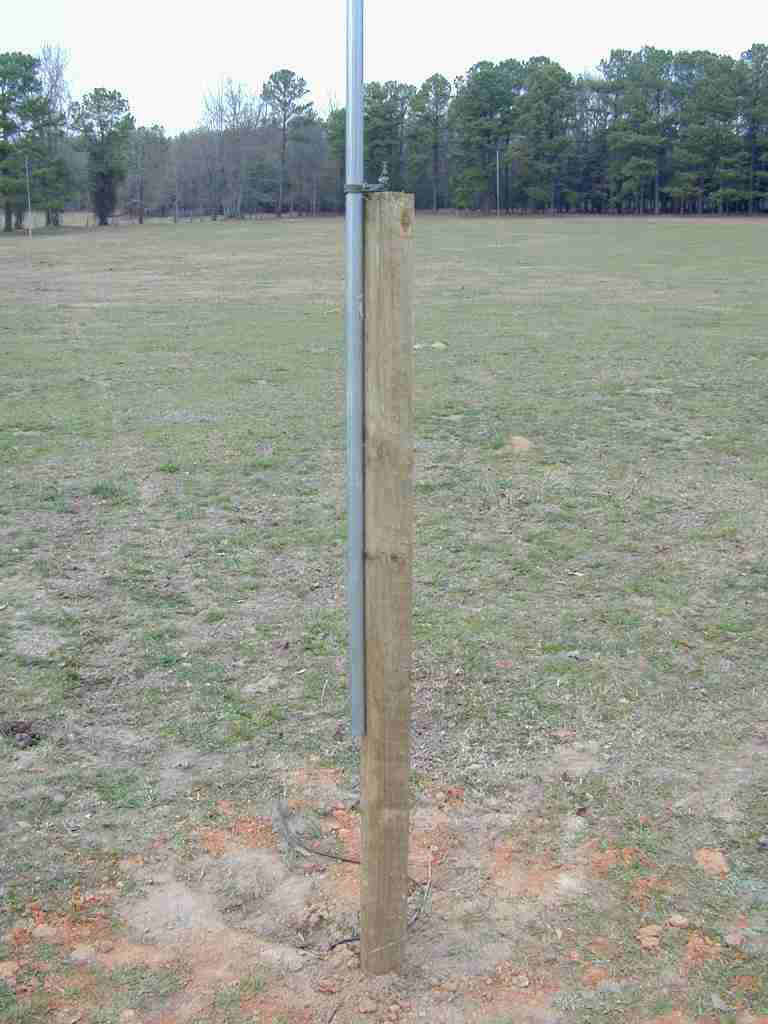
Receiving AntennasMy receiving antennas are in a constant state of change, but are gradually settling down to a few optimum configurations. The picture below was the very start of an 8 circle vertical array installed in 1999. My first directional small vertical arrays were installed in the 1980's. My first loop array of phased loop antennas were installed in the 1970's. I have about 40 years of receiving antenna work with small loops, beverages, and other arrays.
Above....Eight vertical receiving array in a rear field.
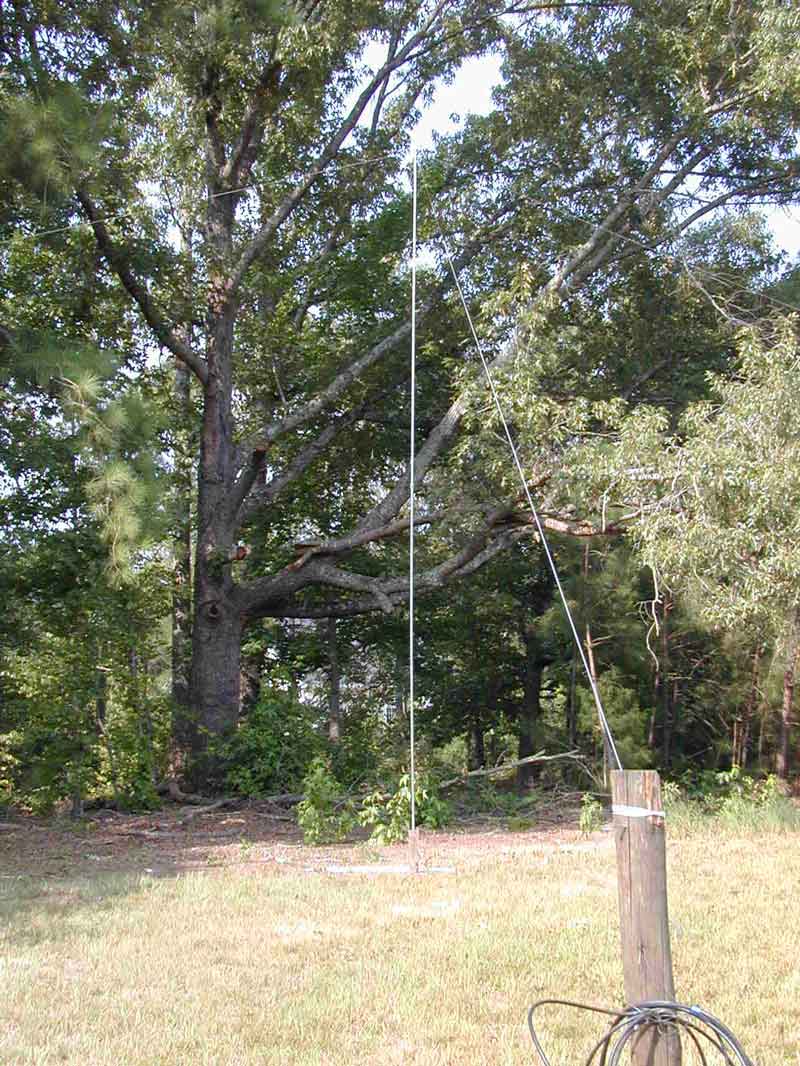
Below, elements in my Europe 4-element vertical array. This array is spaced about 70 feet endfire and 330 feet broadside.
Above....Front vertical array area. Typical element construction. Receiving antenna details page
|