
Also see Radiated and Conducted Noise
Distribution lines are the high voltage lines that distribute power along residential and light commercial feeds. Many years ago these lines were just over 2200 volts, then 4160 volts (from primary to neutral) became a standard. Many amateurs used surplus 4160 transformers in power supplies! I once had a 572B amplifier using a 4160 pole pig. The line voltage switch (2.5% taps) was at the middle of the winding, making a great center tapped winding. Back around 1970, I ran about 2900 volts on the plates of four Cetron 572B's.
In the 1970's, I started building noise locating equipment and repairing noise locating equipment for utilities. 1980's and later, I subcontracted work for a few small (and one major) companies locating more difficult cases of power line noise. As I quit working with utilities, most residential system were 7200 volts from primary to neutral. My local feed today, on a rural dirt road with single phase, is 7200 volts.
Distribution power line noise is
generally a raspy
buzz. Power line generated noise on normal distribution lines is modulated at
some low harmonic of
the power line
frequency.
Almost always the single phase "buzz" is 120 Hz. This is because noise
is from small arcs (usually in insulators or pins), and the arc almost always occurs twice in each cycle near the
negative and positive voltage peaks
of the 60 Hz sinewave. Power line noise is broadband. Power line noise does not
appear in clusters or periodically across any given band, although level can
change greatly from band to band.
Switching noise and digital noise from
consumer devices is almost always periodic. The periodic appearance across a
given band occurs because most consumer noise is generated by a high frequency
clock or oscillator's harmonics. If the time base or oscillator of the consumer
device is 30 kHz, noise generally appears every 30 kHz across a band. There will
generally (but not always) be clear spots between noise peaks.
Some forms of modern digital noise can sound like power line noise.
One example is my neighbor's Direct TV recorder system. The Direct TV device
they have far exceeds FCC emission limits. From mid-AM broadcast band to mid HF,
it sounds just like a residential distribution power line noise and the raspy
buzz it generates follows the power lines. It disappears above 10 MHz.
Transmission line systems, the really big lines running from town-to-town, run at much higher voltage. Because of that, the noise is generally different. The noise ranges from a sharper buzz to a hissing with a faint 120 Hz or higher note. High voltage transmission line noise can sneak up on us, making us think we have normal background noise because at times it blends into normal background hiss. This is because the arc or discharge, being from a much higher voltage, often lasts over a much larger portion of the cycle. It also can involve multiple phases. This smoothes or softens the noise, but if you listen carefully there is generally a little 120 Hz, 240 Hz, or 360 Hz slightly musical buzzing present.
Power line noise is relatively frequency independent, usually having only a very gradual change in level with frequency. Power line noise can be band specific, but it is never frequency specific. Light dimmers and other consumer devices can be the same.
If a noise is frequency periodic, especially a signal repeating with 10 kHz or more spacing between peaks, it is probably a switching power supply or digital device of some type.
CB jargon sometimes mistakenly refers to line noise as land-noise or ground-noise, very unusual slang since neither the ground nor the land is a source of noise.
Distribution system power line noises originate in the following items, each of which has subtle but unique characteristics in pitch or sound. Some sources also start and stop in response to weather:
These arcs are primarily, but not always, dry-weather noises.
This type of noise is generally a higher-pitch raspy or rough noise. Pin noise or hardware arcs between loose pieces of metal on the pole almost always go away in wet weather. This is because moisture wets the dielectric (oxide or corrosion) in the pin area making it conductive, and that stops the arc. This particular noise source also "breaks up" when poles and wires wiggle or move. When I did noise investigation for a few utility companies, I would strike the suspected pole with a large hammer and listen for the noise to "break up". Another method I used (after looking to see the guy wires were well clear of any hot lines) was to shake or push on guy wires. You should not do this without permission of the pole owner. I had permission.
Insulator pin arcs are one of the most common sources of broadband noise on power lines. This noise is caused by low tension on bell insulators, allowing them to hang with visible sag or slack. The noise is generally a medium to low level noise with a higher sounding smoother pitch because the arc is weak with very low current, but like all noises it can propagate a long distance along the lines.

The pins on each end of insulators can be a common source of noise. The long insulator above is a newer Polymer type. It does not have the leakage capacitance of older ceramic bell insulators, and is not as noisy when span tension is low. The pins however are the same in almost all insulators. With low tension the pins corrode and make poor contact. This can cause a very tiny arc. The arc excites the power line through the insulator's stray capacitance and the power line acts like a giant antenna. A few milliwatts of energy can radiate a long distance when using a long wire antenna like a power line!
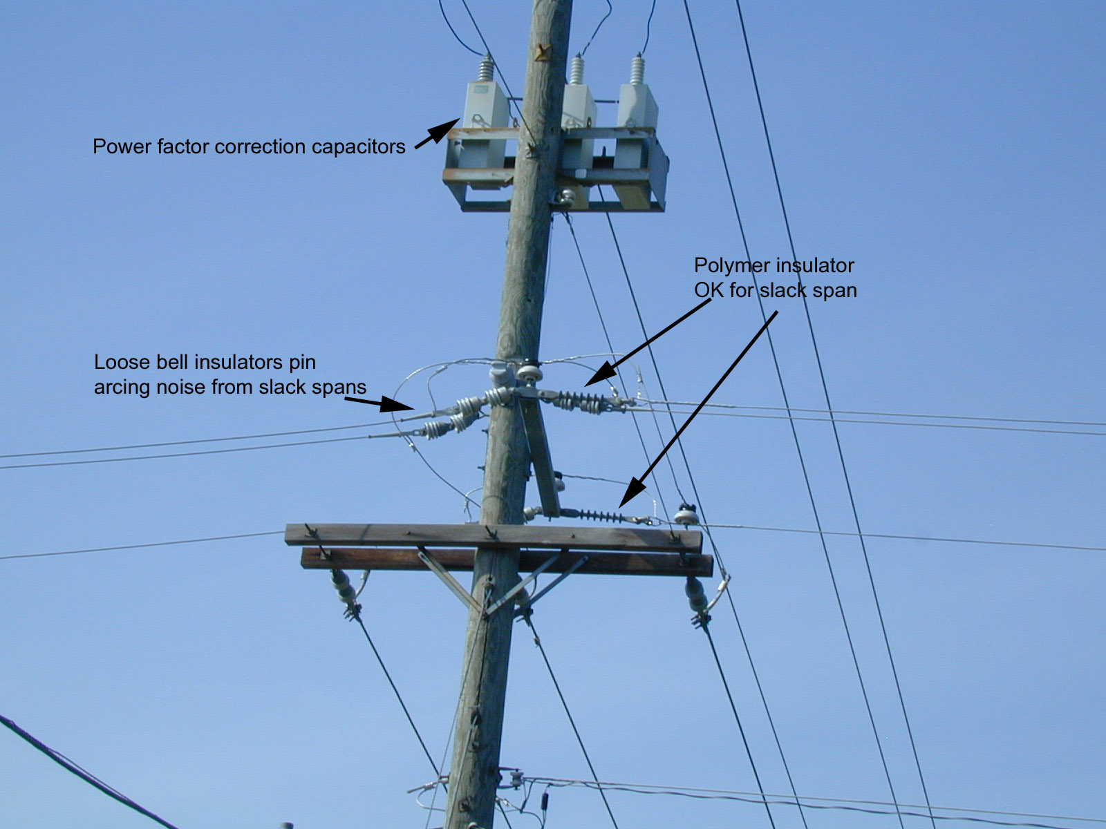
Loose connections on power factor correction capacitors can arc for many years without damaging anything. This is generally an all weather noise.
The bracket of the capacitors should be grounded to the pole ground wire, and the capacitor, solidly. Not bonding generally makes a dry weather noise, and is a safety hazard to workers
Polymer insulators can have slack spans or low tension with little likelihood of noise. Since they are very long and have very low end-to-end capacitance, they are unlikely to have enough voltage at the pole end to arc, even when loose. They are good trouble-free insulators.
Loose ceramic bell insulators are bad news, especially in dry weather! The large metal caps towards the pole side capacitive couple to the hot wire side. This bell-style insulator has considerable capacitance from the hot end of the insulator to the ground end. It should never be used in slack spans. Slack spans should use post mounted insulators or long polymers to minimize capacitance and increase leakage path between the ends.
Most often a noise problem with slack spans is rooted more in the capacitance of the insulator than actual leakage across the insulator surface, although both can be involved.
The longer polymer insulators on the pole above have a long fiberglass rod core and a very long external leakage path around the ribs. Ceramic bell insulators have a very large metal casting capping the low voltage or grounded end, and have an interlocked center pin and body cap separated by ceramic. Spacing is small and parallel surface areas are large in the more compact ceramic insulators, causing very high capacitance between the metal cap and the center pin of the ceramic insulator. The longer multi-ribbed polymer insulators have very low capacitance and a long leakage path, so they do not couple from end-to-end nearly as well as the ceramic bell insulators. A span might have to be left slack if the pole can not be back-guyed. Polymer insulators are preferred when a span has to be left slack.
Pins that secure the insulator to the hardware will corrode and build up a thin layer of insulation. When a span is slack (under low tension) the insulator metal end cap, the floating pin that locks the end cap to the eye bolt or mounting hardware, and the mounting hardware will arc across the thing layer of corrosion in the joints. This is because the pin is not pulled tightly against the mounting hardware and a small arc develops across the corrosion in the joint. In wet weather the arcing will often stop and the line become quiet. Slack spans with bell insulators are mostly a dry weather problem.
Loose hardware on poles and wires is a common problem. It is also a safety issue! This type of problem generally makes a severe raspy strong noise over all bands. This type of noise is generally unaffected by moisture, although it can get get either louder or quieter in rain. If it is arcing from something being ungrounded, noise will generally go away in the rain. If it is a loose connection on a through connection, like a loose nut on the transformer primary connection, it will come and go, being largely independent of moisture.
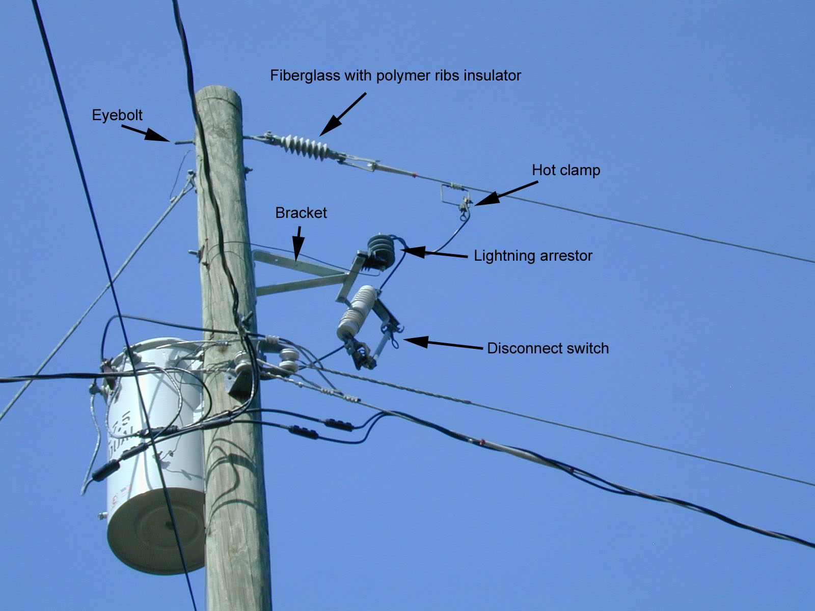
All metallic hardware should be solidly bonded to the ground wire on the pole or it should be well-insulated from anything else. This is important for minimizing radio noise as well as protecting utility workers. It also reduces the chances of lightning damage.
Note the eyebolt at pole top is grounded through a wire to the guy wire and the vertical ground wire running up the pole.
All hardware should ground to the pole ground. The bracket to the left, for example, should be securely grounded to the ground wire running down the pole.
Notice this utility let the bracket float. (the line that might be a ground wire to the bracket is actually a shadow)
While a well-insulated ungrounded bracket won't make noise, it does create a safety hazard to linemen.
If the disconnect switch insulator should ever arc through, develop leakage, or crack the bracket would become hot. If the lightning arrestor would fail shorted and blow its ground wire off, then the bracket could have full primary voltage. If the ground wire was close but not touching the ground wire, it could arc from normal leakage and cause radio noise. The bracket either needs to be a long distance away from the ground wire, or it needs to be bonded to the ground wire. The best installation would bond the bracket into the pole ground wire.
The eyebolt holding the polymer insulator should also either be solidly grounded, or it should be kept away from the ground wire. Again the safest installation for linemen would be with a grounded bracket.
Hot clamps and other line hardware should be tight. Some of the most severe noise sources are loose hot clamps and corroded disconnect switches. Loose connections can actually start fires in dry weather.
Ballasts in street lamps can also be a problem.
Off-on buzzing noises, timed with a regular rhythm, are often small permanently wired electric transformers, heating pads, fish tank heaters, and older electric fences.
Electric fences are generally about 1 second on and one second off. Noises are caused by bad splices and connections, or wires contacting something that causes a small arc.
Small transformers often have a thermal cutoff switch. They usually pulse slower than an electric fence. The general cause is a shorted secondary circuit, which in turn overheats the transformer and causes the thermal bimetal overload switch to cycle off and on as the transformer winding heats and cools internally. Small heating pads are similar in time.
Heating elements for fish tanks and large electric blankets are often very slow in cycling with long off times.
Frequency-periodic drifting signals are usually switching power supplies of some type.
Really broadband almost indescribable trash that is almost white noise often comes from plasma TV sets.
Locating Noise
For you own noise locating equipment, it is best to use AM detection. It is important that any impulse or arc detector use a wide IF bandwidth and AM detection. AM broadcast receivers work after a fashion, but make localizing noise to one particular pole difficult or impossible. This is because the wavelength of the AM band is very long. Wires and conductors along the electric system conduct longer wavelength noise with very little attenuation. Another effect is standing waves, which can make the same noise peak and null as the receiver moves along the wires. The combination of low attenuation with distance and standing waves along the wires can make it very difficult to pin down the exact source. As such, AM receivers have very limited utility for narrowing down source locations.
The very best receivers are VHF or UHF AM receivers, like old television field strength meters. Another commonly available and relatively inexpensive receiver is a regular portable aircraft receiver. A few FM portables or mobiles for amateur use include aircraft band, or selectable AM detection.
Commercial Gear
This is a very wide tuning range battery-powered receiver with a wide IF bandwidth. It has an AM detector and attenuator. This Sprague noise interference locator was typical of handheld noise locating devices used by utility companies. It is one of many RFI locators I used when doing consulting. It tunes from the low AM broadcast range up to UHF in one tuning range!
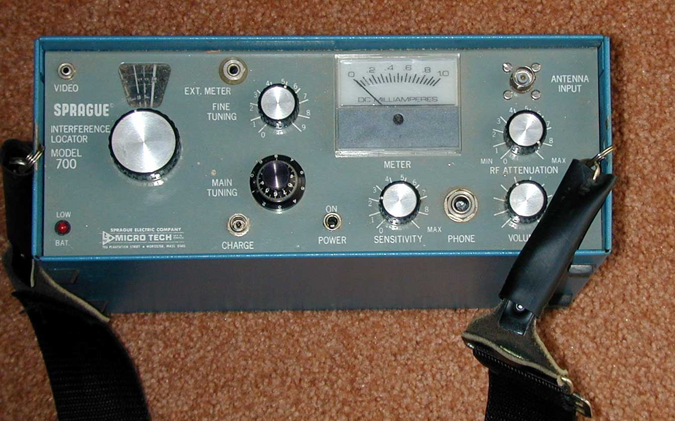
The basic receiver is very much like homemade units I built for utility companies.
My units used two detectors. The first detector used a variable capacitor tuned local oscillator and mixer. It up converted to a 40 MHz IF system driving a video detector. The IF system was actually an IF and video detector module from a standard TV set. I switched between the low frequency mixer (40 MHz down) to television set varactor VHF and UHF tuners.
This commercial unit is very similar. It up converts to a UHF TV tuner and IF system. A single dial tunes from below the AM broadcast band to UHF.
This unit has an internal battery, and uses several different hand-held antennas shown below in order of descending frequency.

upper VHF and UHF directional antenna
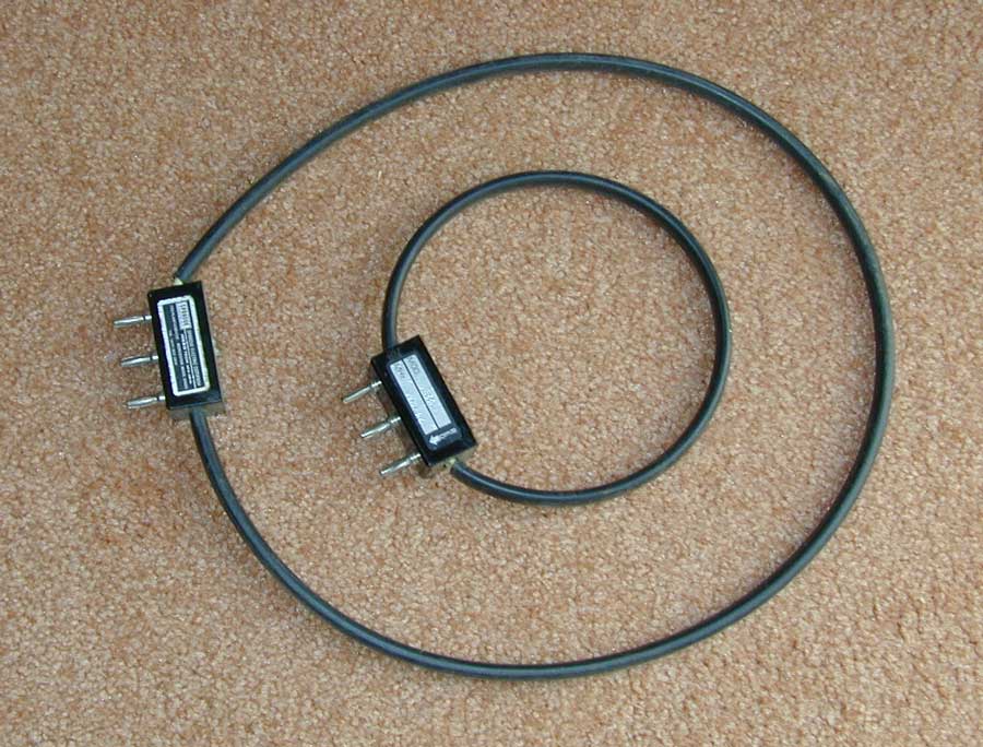
Low VHF to upper HF loop, inside a bigger mid to upper HF loop.
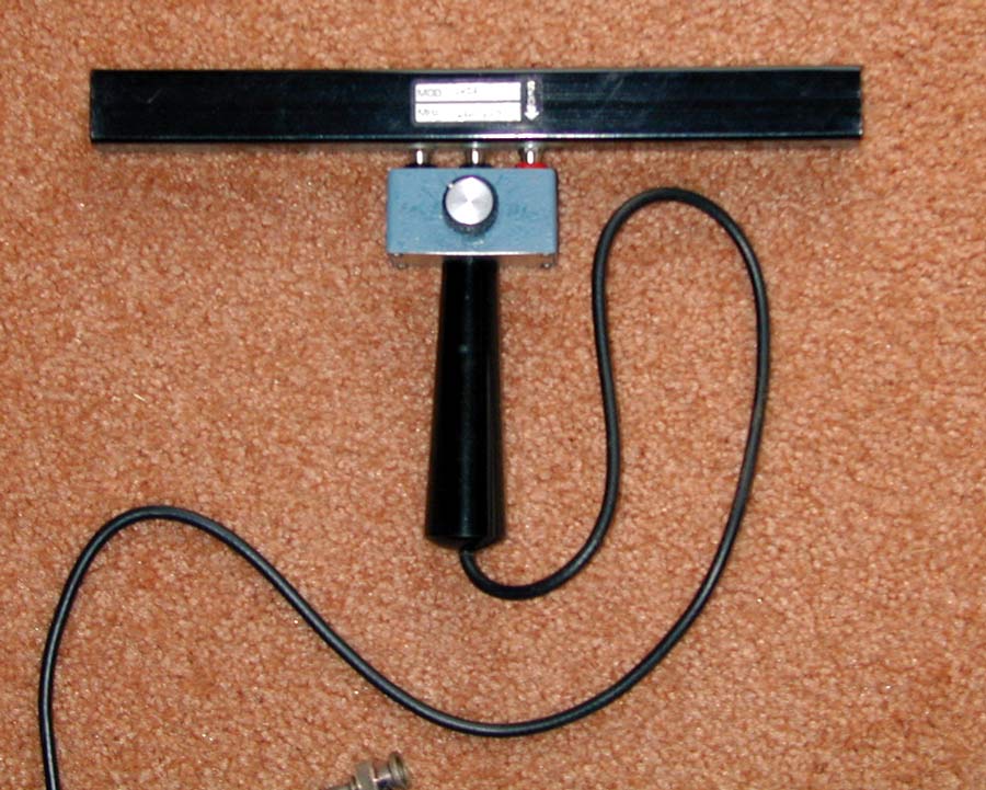
Broadcast to mid-HF rod antenna.
This rod antenna is plugged into the hand unit that contains the tuning capacitor.
The rod antenna is bidirectional.
This is a home brew loop I made. It includes a built in amplifier and band switches from AM broadcast up through 10 MHz.. I also use it in conjunction with a MFJ-259B meter to locate buried cables. I can find the location of underground cables within one inch using this loop!
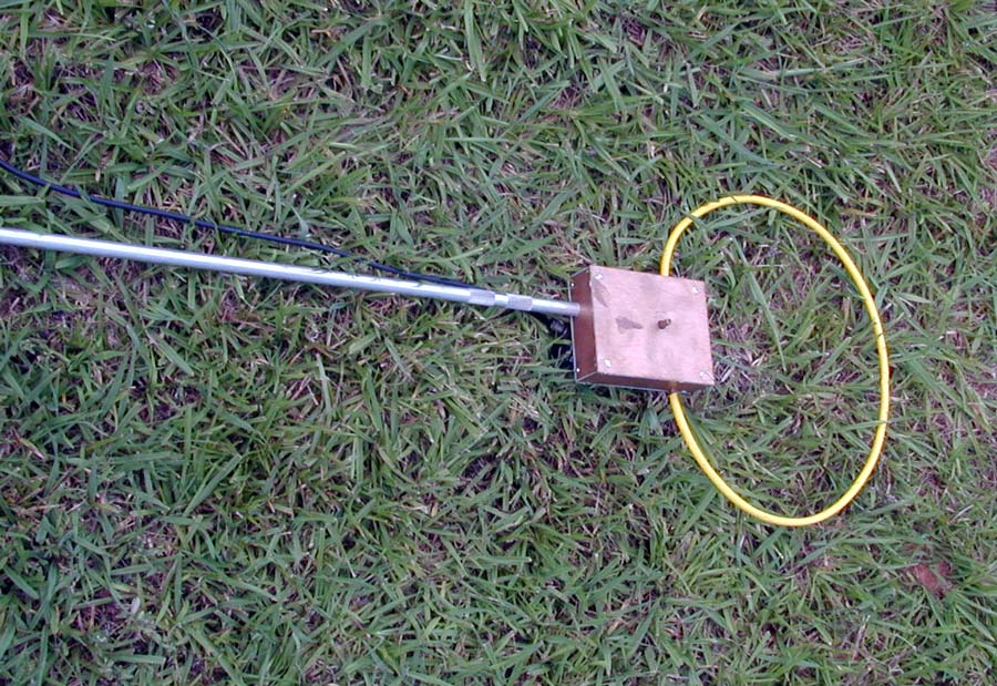
The yellow area is yellow heat shrink over 5/16th inch copper tubing. The gap or split in the tubing is at the very top, opposite the copper tuning box.
The bottom ends of the copper tubing run through and solder to the copper box. Multiple turns inside are tapped by a switch, and tuned by a 200 PF variable capacitor
This loop, because it employs a JFET amplifier, is very sensitive.
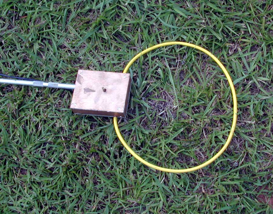
The null is though the loop center.
This loop makes an excellent cable locator.
I easily find the location of underground cables with this loop and a small signal source, like the MFJ-259B.