For the summary page click here pre amp_summary
The following is a comparison of HF low noise receiving preamplifiers. More amplifiers will be added as they become available to test. All instruments used for these measurements are currently calibrated newer-production laboratory grade instruments.
Detailed graphs will only be added if specifically required. The .jpg pictures on this page are examples of how measurements are displayed on the instruments used in tests.
Gain Compression Tests
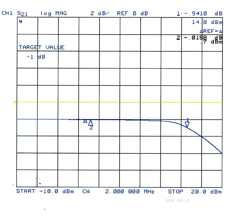
Pre-amplifier gain compression is measured on an HP (Agilent) Vector Network Analyzer and S-parameter test set using the power level sweep function at 2 MHz. A gain compression test shows loss of gain as input power is increased, or the input level where the amplifier starts to saturate.
This test indicates how much overall signal power the amplifier will handle before gain is reduced by non-linearity or saturation. This is power or gain non-linearity, and really does not directly represent distortion level vs. input or output signal power. A correction is applied to results for amplifier gain and equipment protection attenuators.
Note: Third-order intercept is a better demonstration of signal level capacity. Third-order intercept better indicates immunity of an amplifier to producing unwanted signals (mixing products) from multiple strong signals.
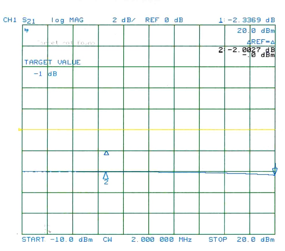
ARR 1-30
Amplifier input power (horizontal sweep) is 3dB per division. Measured 1dB compression is corrected to 21.5dBm output power @1dB compression.
ARR GAsFET (1.8-2 MHz model)
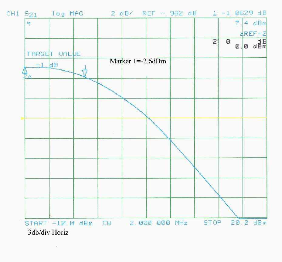
1dB compression is corrected to 8.1dBm output power.
DX Engineering Push-pull HF preamplifier
Gain compression beyond power output limit of analyzer. In other words, my test equipment does not have enough output power to drive the RPA-1 preamplifier into compression. Actual corrected gain compression (manual test) is approximately +26dBm (400-milliwatts output).
Comparison of Third Order Intercept
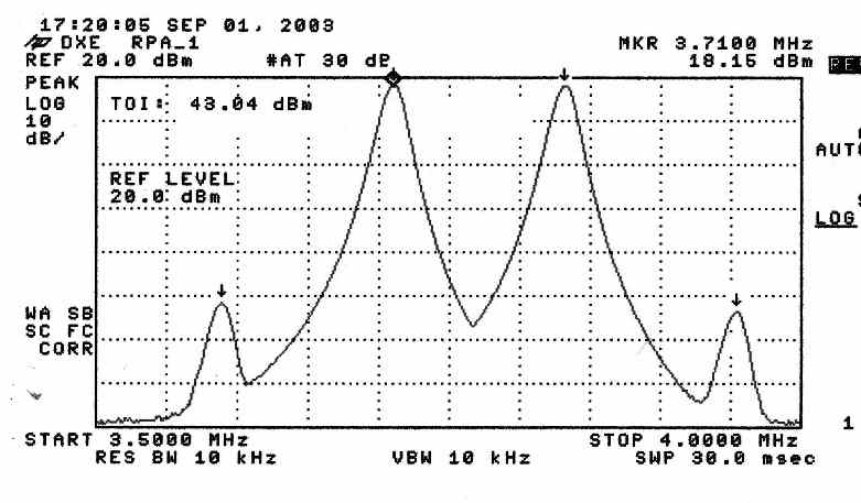
Third-order intercept tells us the immunity of the amplifier to generating spurious signals in the presence of multiple strong signals. This test was at 1.85MHz using the automatic IM3 test measurement. A stepped attenuator pad at the amplifier output was initially used to prevent analyzer damage during testing. Because of this "protection" attenuator, actual TOI must be increased by adding the attenuator value to the analyzer display reading.
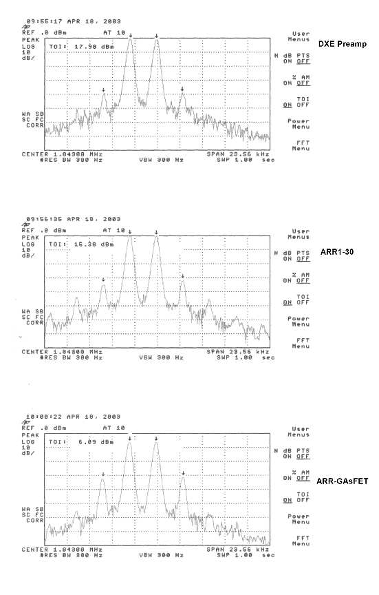
Third-order IM3 levels occur at the following single tone (of an equal two-tone test):
DXE (early model) -0dBm input power (instrument TOI 17.98+20.2dB pad= 38.18dB TOI)
Note: Later model RPA-1 measured 43dB third order intercept
ARR P1-30 -5dBm input power (instrument TOI 15.38dB+15dB pad= 30.38dB TOI)
ARR GAsFET -16dBm input power (instrument TOI 6.09dB+5.3dB pad= 11.39dB TOI)
If you look at the above measurements, you will see third-order intercept in the DX Engineering amplifier occurs almost 8dB higher than in the better performing of the two ARR amplifiers that were tested. Not only is the DXE 3rd order intercept higher, higher order products are substantially less than the other two amplifiers produced.
DXE-RPA-1 Test
This is a later model DXE preamplifier model RPA-1. This measurement has no external attenuator, TOI in this case is a direct reading.
Preamp Noise Figure
I don't have this data saved to a file yet, but the noise figure of the GAsFET amplifier and the DXE amplifier are about the same. The ARR 1-30 had the highest noise figure, about 5.5dB. All of these amplifiers are acceptable for HF receiving in most applications so far as noise figure is concerned.
Input Impedance and Gain
So far, the DXE pre-amplifier has the closest match to 50-ohms over the range of 300kHz to 30 MHz. Gain is also reasonably flat in the DXE amplifier.
DX Engineering Preamp
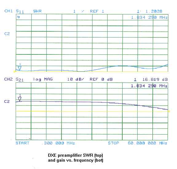
The display above shows input SWR of the amplifier on the top graph, and gain on the lower graph. The marker is at 1.834290 MHz. The vertical graph lines are frequency at about 6 MHz per division. Gain at marker frequency is indicated as 16.819dB, SWR is 1.2028:1.
It is also possible to display input impedance on a Smith Chart:
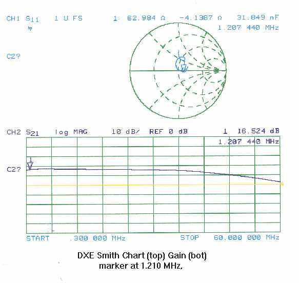
This is the gain and input impedance at 1.207440 MHz.
ARR GAsFET PreAmplifier
This amplifier is intended to be a 160-meter only amplifier. It has high gain despite of the very poor match on any frequency. It also has substantial gain on all frequencies swept, but a strong peak on 1.8 MHz.
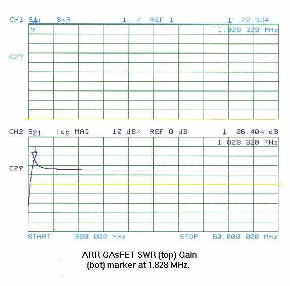
Input SWR is
23:1, gain is
26.4dB.
Unfortunately noise
figure is not that
good for a GAsFET,
probably because of
the very large input
mismatch.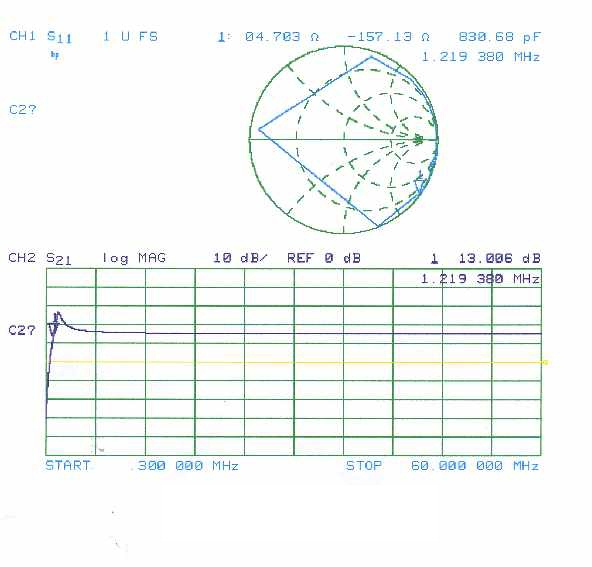
The above data is a Smith Chart display of the ARR GAsFET at 1.22 MHz. Gain is still 13dB, input impedance is 5 ohms and very reactive (this measurement is in the BCB). Despite being a "160-only" amplifier this amp has substantial gain (~15dB) at 60MHz.
Other Data
If you have a commercial amplifier or commonly available homebrew amplifier design you would like tested, please contact me. I'd be happy to measure your amplifier (time permitting) and post the results here.
See (soon to be added) summary page for text comparisons.