[ Home ]
The following short article is about shields, Litz wire, braid, and skin depth.
Related pages
Coaxial Cable Leakage
Common Mode Current
We occasionally hear that time-varying magnetic fields penetrate a non-ferrous "shield" on a shielded loop or coaxial cable, while electric fields are blocked. Here is an easy to replicate experiment showing how a thin copper wall behaves at radio frequencies.
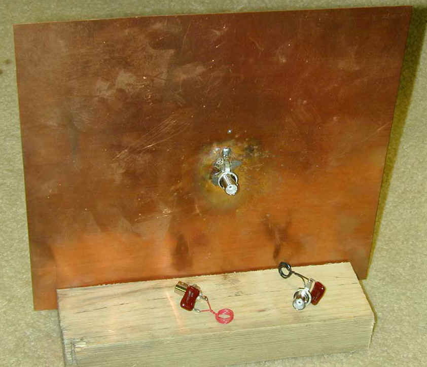
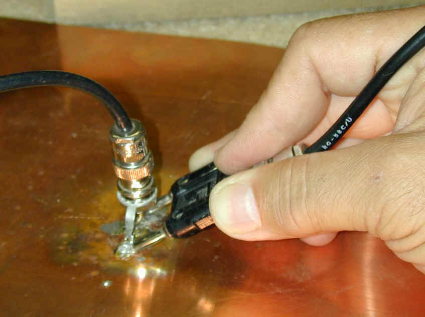
Below. I used a 10-inch square ~.015 inch thick copper sheet. A standard BNC connector was soldered to the center of this sheet. (The lower foreground shows two small magnetic pick up coils about 1/2 inch diameter)....
BELOW. The rear of the sheet has two tabs positioned directly opposite the BNC connector connections. These tabs mark the exact location of the BNC center and shield pins....
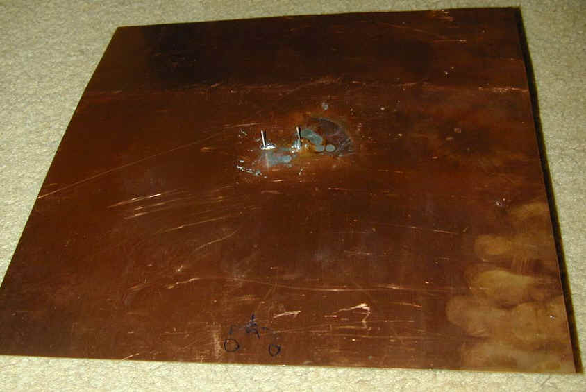
These tabs provide a reference point for measurements directly opposite the BNC connector on the rear wall of the sheet. Only a very thin wall of copper 15/1000th inch thick (.015" thick) separates the rear terminals from the front side BNC connector connection points.
Is it possible for energy to flow directly through the 15/1000th inch thick copper wall? How would the signal get to the back side of the wall? To answer these questions we can make two basic measurements over the area of the sheet.
We can move the probes and loops over the surface to map signal levels.
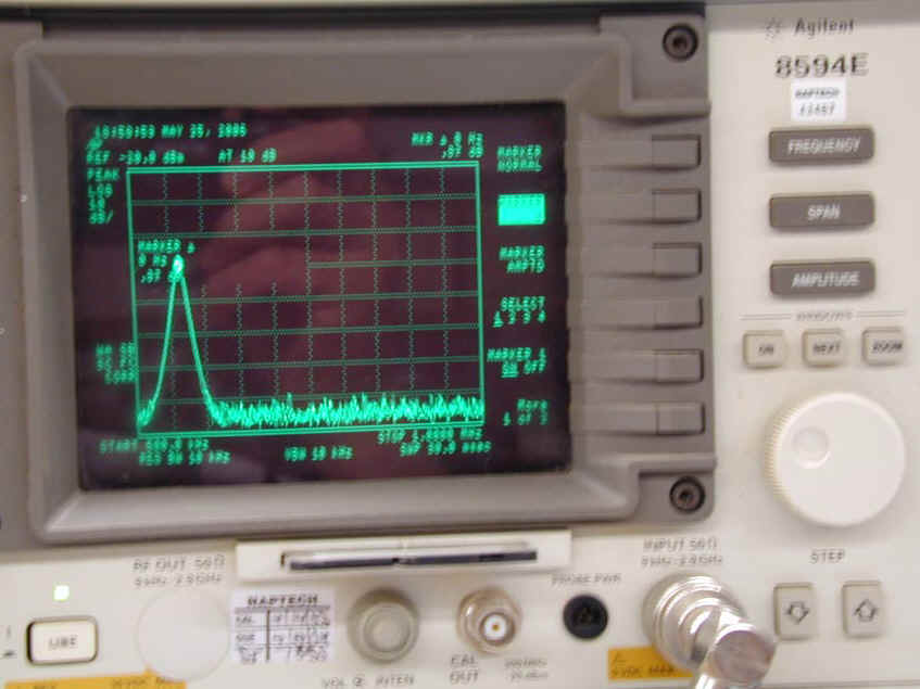
The most convenient device I have for measuring level change is my spectrum analyzer with a marker delta function. By placing a probe at the injection point where a high level signal is injected and zeroing the marker delta function, we can directly read the difference in signal levels at other points.
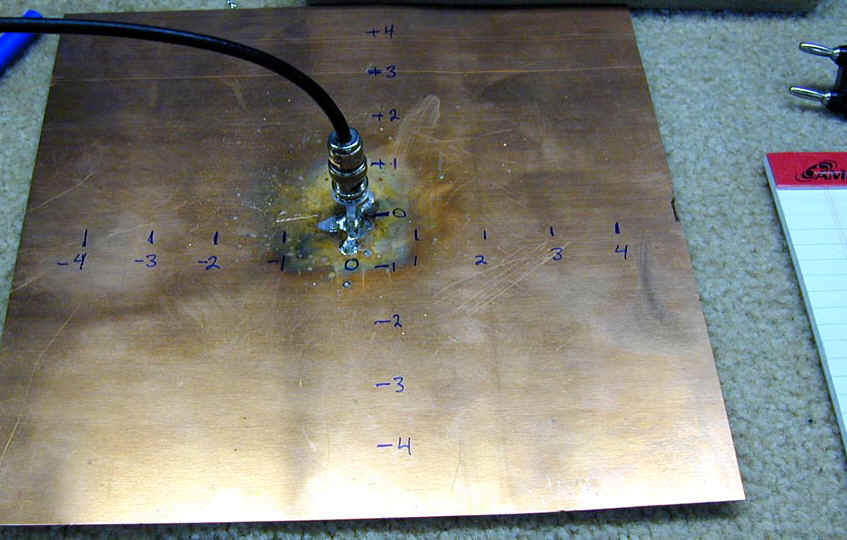
Below. The copper sheet is marked in inches....
BELOW. The analyzer probe is connected and the marker zero button pressed. Now we have a reference level of zero dB...
BELOW. The probe is moved laterally one inch. The analyzer indicates signal level change...
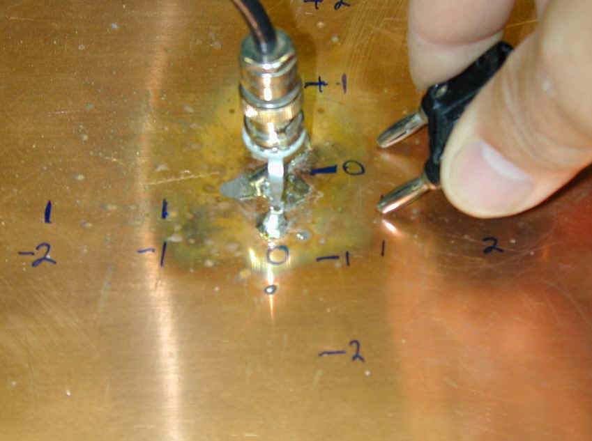
BELOW. The probe contact point is moved outwards and once again the analyzer indicates level change...
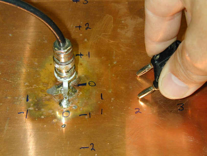
The connection points are moved one inch at a time all the way around to the rear. The last measurement is at the two terminals exactly behind the generator input connector.
How much signal do you think there is directly behind the generator attachment point? This point would have only .015 inch of copper wall thickness separating the terminals. Do you think the path directly through the .015 inch thick copper wall would have more level than a lateral move of one inch, where the signal has to flow laterally one inch to one terminal and then back laterally for a total of two inches? Does the .030 inch round trip directly through the wall have less attenuation than a lateral trip of at least two inches?
The following readings were observed at 500kHz:
| Front | front edge | rear edge | rear center | |||||
| 0" = 0db | 1" = -11dB | 2" = -24dB | 3" = -35dB | 4" = -43dB | 5" = -55dB | 5"= -65dB | 4" = in noise | in noise |
We see signal level decreases steadily towards the edge. As we work around to the other side, we find no measurable signal directly through the very thin copper wall!
This proves the skin depth of the copper prevents coupling to the far side. The isolation is as good as if the back side were totally isolated from the front, except for what spills over the edge of course.
What happens when small loop probes are substituted for direct connections? The small loop probes are resonated at 6.5 MHz. One loop was fixed at the center, the other was moved along the surface. The loop was always aligned for maximum reading. The following readings were obtained at 6.5 MHz::
| Front | front edge | rear edge | rear center | |||||
| 0" = 0db | 1" = -20dB | 2" = -38dB | 3" = -46dB | 4" = -53dB | 5" = -55dB | 5"= -62dB | 4" = in noise | in noise |
Neither time varying magnetic flux nor time-varying electric flux can pass directly through a conductive wall more than several skin depths thick. A shielded or coaxial loop only receives signals from the outside wall, with the gap becoming the feedpoint. Our Handbooks are correct. The outer wall of a coaxial cable is a "third conductor", the outer wall is isolated from the inner shield wall by skin effect.
Don't confuse an intentionally gapped screen with a completely walled or closed screen. Each behaves differently.
This is a Faraday Screen etched on a double sided PC board. I developed this screen in the 1980's for a medical application...
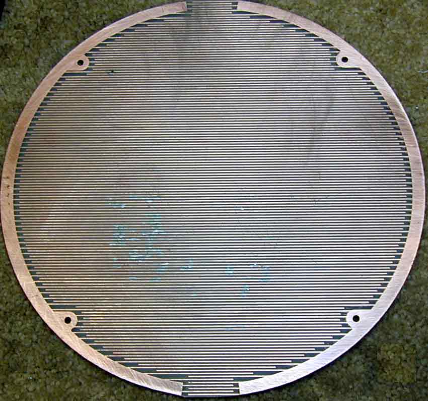
(This applicator design is patented.) To satisfy FDA requirements, we had to make hundreds of E and H field measurements. We need to provide a stable magnetic field level. To reduce the effect of applicator-patient spacing on tuning, and to prevent dielectric heating of areas near the surface, I needed to reduce direct capacitive coupling to high voltage points inside the applicator.
This applicator consisted of a large pancake coil inside a metal "pan". The pancake coil had a large fixed copper plate at the center, and the outer edge was grounded to the pan. A movable flapper-plate, grounded to the metal coil-enclosure pan and centered on the fixed coil plate, tuned the pancake coil. The large center plate had considerable voltage, and considerable capacitance to anything placed within a few inches of the applicator face. This meant anything near the applicator center had large displacement currents, which seriously affected tuning and impedance.
My solution was installation of a unique "Faraday" screen. My screen employed a double sided PC board, with opposing screens on both the inner and outer surfaces. The inner interlaced screen was rotated 90-degrees from the outer screen. This spread the electric field around over a wide area, preventing a concentrated electrical field from appearing. The screen prevented direct capacitive coupling, and reduced distance detuning of the application and E-field heating of skin. This helped produce a more consistent field intensity level deep in a patient's soft tissue.
Many people think a screen like this reduces electric field to zero, by shielding or screen the electric field. Factually, we cannot have a time varying magnetic field without an accompanying time-varying electric field. What we can do is change the field impedance by moving the field around, or changing the ratio of electric to magnetic fields. In a screen like this, the electric field is concentrated at each open tip. Since alternating open tips appear everywhere around the applicator's perimeter, the electric field is evenly distributed without "hot spots". This reduces direct external coupling through capacitance to nearby objects.
This screen does not eliminate the electric field. If it did, all magnetic coupling would also stop. Just a few inches from the surface, the field is nearly identical to an unscreened applicator. This screen and similar screens will reduce direct capacitive coupling to objects a very small distance away, but they do NOT take the electric field to zero as some people might claim.
If this screen were solid, neither magnetic or electric fields would penetrate the wall. Any excitation of the other side could only come from current spilling over the screen edge. This is because skin depth prevents magnetic and electric fields from penetrating any conductor more than several skin depths thick.
The best explanation of skin depth I have seen is in Circuits and Networks (by Koehler) on page 196:
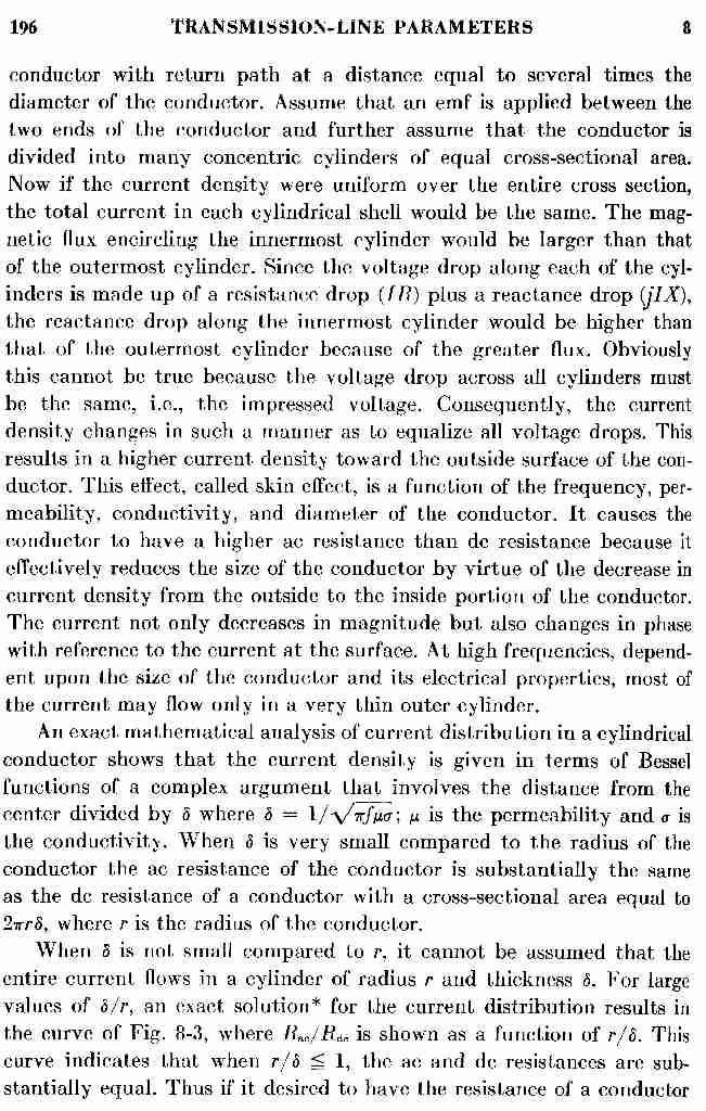
So we see, skin effect occurs because the outer areas of a conductor have less magnetic flux surrounding them than the inner layers. While we often consider the effect on materials without weaves, think about how this affects woven conductors like braiding or Litz wire. Any individual conductor has HIGHER impedance when it moves into the center areas, and if current finds an alternate path it moves out to the lower-impedance outer layer.
If strands touch with high resistance connections, it effectively adds unnecessary resistance to the path. The fact the surface is rough also DECREASES effective surface area for current for a given occupied physical area, because there are non-conductive air gaps in the occupied area!
The increased resistance (and impedance) is why braiding should never be used for high frequency high current applications unless it is oversized to compensate for increased impedance and dissipation. Parallel stranding decreases effective current carrying surface area at high frequencies, but at least avoids the weave problems.
As a matter of fact the weave is what causes most of the loss increase when typical coaxial cables are contaminated by water. The problem occurs, even after the cable is dry, because the hundreds of weave contact points corrode and make poor connections, increasing the resistance. Something similar happens when we "unpack" a braid from a jacket. The pressure between weaves decreases, and series resistance (and impedance) increases!
We could insulate strands, and once we establish a basic loss in conductivity caused by replacing useful conductor area with insulation we would find the impedance slope much flatter with frequency. If the strands are insulated (Litz wire) and frequency is increased, eventually we reach a point where the conductor resistance increases and we are much worse off than we would be with braided or stranded wire. The upper limit point is generally around 1 MHz for Litz wire.
From Radio Engineering by Terman:
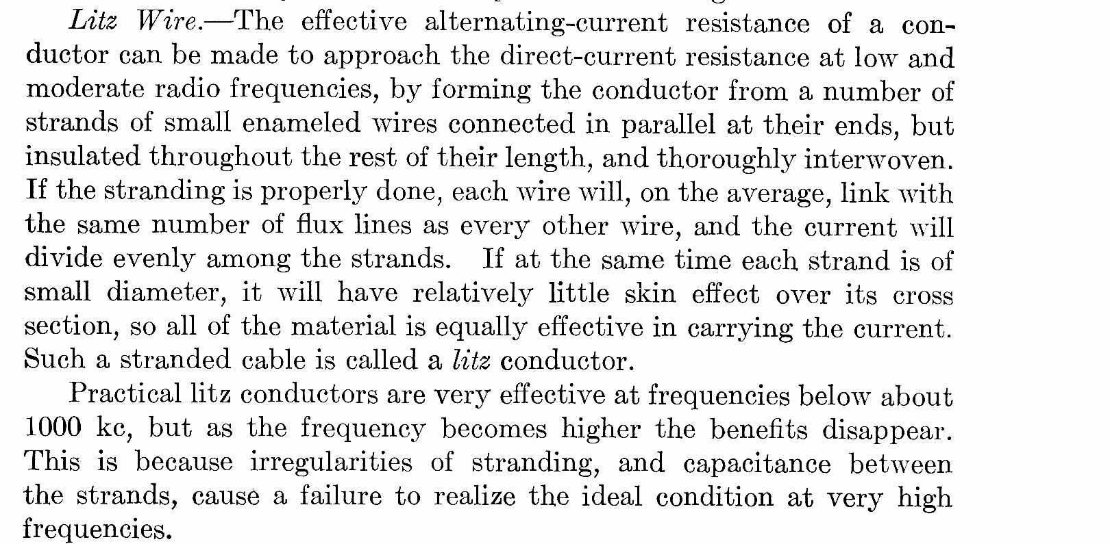
In reality, the real advantage of Litz wire is NOT reduced resistance per unit length for a given diameter. The advantage is less slope in resistance with frequency and reduced eddy current when the conductor is in a multi-layer coil or transformer. The individual strands are like laminations in a transformer core, and below a certain frequency they greatly reduce eddy currents by decreasing the "short circuit" path distance for magnetic flux induced currents that are not in the normal current flow direction.
My own measurements have shown noticeably lower ESR (equivalent series resistance) for a given conductor size when using a SOLID wire as compared to any Litz wire sample I have tried above 300kHz (the lower limit of my main vector network analyzers).
For a given wire diameter and form factor, I've always been able to achieve higher Q with solid round or ribbon conductors.
Also see mobile and loaded antennas.
this page since October 2005