Sleeve Baluns
also see common mode isolation
Sleeve baluns are normally used at VHF and higher. As a general rule, they are not practical at HF.
The balun can be inverted and used as a skirt to form part of the antenna element. Here is an example:
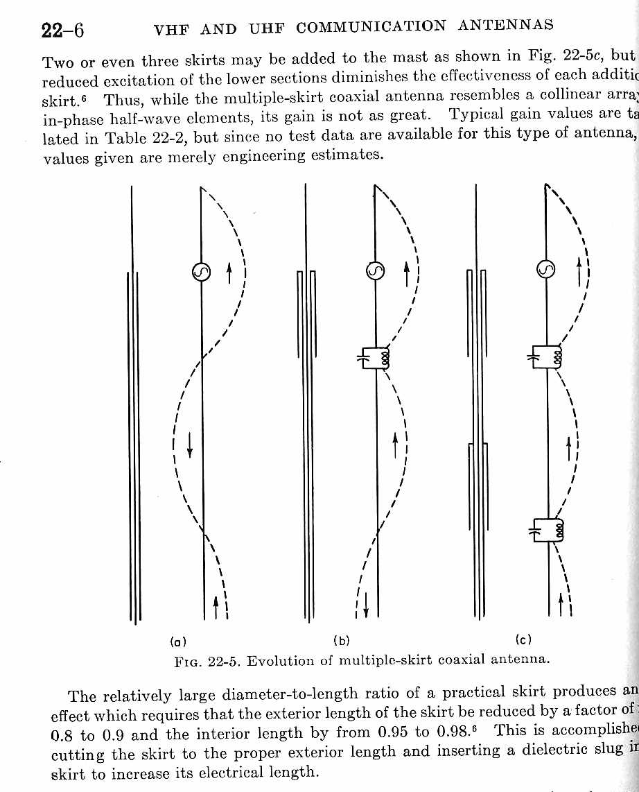
Note at figure 22-5(b), the middle antenna, a skirt does not fully decouple the coax shield.
Many collinear antennas depend on this effect to excite the collinear elements!
Stopping common mode requires both a skirt and radials, or multiple large inside diameter skirts.
Decoupling Impedance
Depending on which layout is mechanically easier to build and if you want the sleeve to radiate, the sleeve can be connected like this or reversed. In the layout below the sleeve is non-radiating. In a collinear antenna we might want to reverse the sleeve so it forms half of a dipole element.
 |
|||
|
|||
The left hand side of the drawing, once past the sleeve connection point, is UNBALANCED. The right hand side is balanced. The choking impedance of the balun is the impedance between the outer sleeve and the outside of the shield of the coaxial cable inside at the open end of the sleeve.
The choking impedance represents the same type of impedance we would have from any common-mode choke, such as a coil of cable or a string of ferrite beads would produce. A sleeve balun only works where it is ¼ wl electrical length, or odd multiple thereof.
Obviously we want the highest possible choking impedance, because the balanced load terminal voltage on the shield side to unbalanced (shorted end side) voltage and impedance sets the current though this balun (as it does with any choke balun).
We can use TLA (free with the purchase of ARRL Antenna Books) to calculate balun’s choking impedance.
Below is a calculation of sleeve balun choking impedance with 100-ohm Zo 1dB loss sleeve. I used a .5vF inside the sleeve.

Balun choking impedance 50-ohm Zo sleeve and .351dB internal sleeve loss (sleeve 35 feet long and matched loss 1dB per hundred feet).
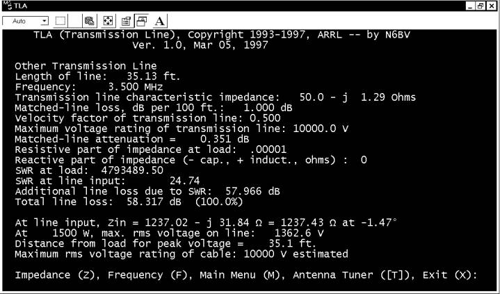
Impedance is now 1237 ohms compared to 2474 ohms for 100-ohm sleeve Zo.
As we double sleeve Zo, all other things equal, choking impedance doubles. What happens if we only change loss in the 100-ohm line? We can do this either by doubling the loss per hundred feet or doubling Vf at the same loss, making the sleeve twice as long (and twice the loss).
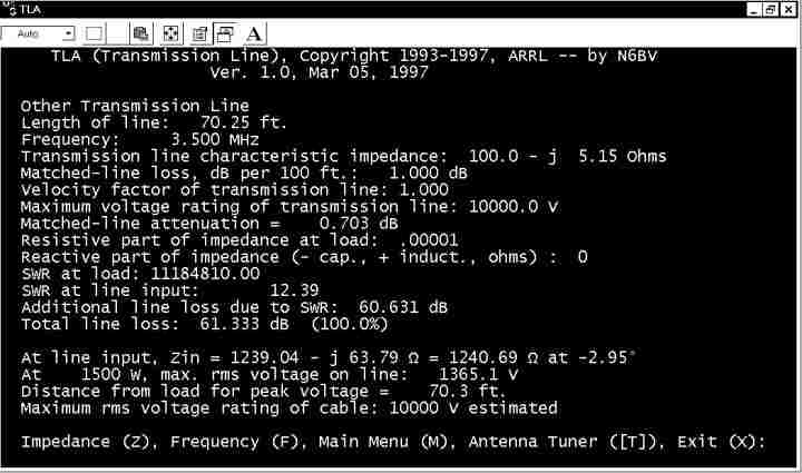
Now we have 1240 ohms with a 100-ohm Zo sleeve. The reason we have less Zo is the attenuation or loss INSIDE the sleeve is twice as high. If you look at Matched Line Attenuation above, it is now .703dB versus .351dB in the 0.5 Vf case.
From
the above, we observe the following characteristics in a sleeve balun:
The cable should have a good low-loss jacket or a very large air or low loss dielectric gap between the shield and the sleeve. Since energy is normally confined to the inside of a coaxial cable manufacturers are not concerned about jacket losses. They use outer materials with long life, not low RF loss. It is advisable to use a filler material with a high volume of air to maximize sleeve impedance and minimize sleeve losses.
It is also advisable to use the largest practical diameter sleeve with the smallest diameter coaxial cable inside to maximize choking impedance.
The sleeve length has to account for velocity factor of the sleeve, since the sleeve forms a coaxial transmission line with the outer conductor of the coaxial cable it is intended to choke or decouple.