Never Pick Gain, F/B, or Take-off Angle as a Parameter for Weak Signal Receiving!
Arrays of small verticals provide excellent receiving performance when systems are designed and installed properly. As pointed out in other articles, there are key differences between receiving and transmitting systems. Parameters considered important in large transmitting systems are sometimes far from optimum in receiving applications, especially systems using small antennas. One key item is gain. Contrary to common opinion, more gain does not translate to better receiving, once the receiver is limited by external noise reaching the receiver. The key parameter is directivity, which may or may not have a parallel relationship with gain. Gain includes efficiency, directivity excludes efficiency. This important consideration applies to systems discussed below.
Noise rarely comes from one direction, or a narrow range of directions. With that in mind, antennas will be compared by a receiving directivity factor calculated with Eznec's (version 3) average gain. Removing efficiency from the equation allows direct comparison of receiving systems since directivity, not gain, is the determining factor in selecting an HF or LF receiving array. S/N ratio is very dependent on nulling or rejecting unwanted signals or noise.
It is important to locate receiving antennas as far as possible from radiators or re-radiators of unwanted signals and noise. Always remember noise has exactly the same characteristics, so far as an antenna is concerned, as signals from intentional transmitters. There is no way to sort "good signals" from "bad noise" except through the directional characteristics of your receiving antenna. Noise is not electric field dominant. Desired signals are not magnetic field dominant. The field impedances are all the same except near the antenna or source, and near the antenna or source coupling to multiple unknown sources is largely unpredictable. The truth is, it is anyone's guess what field impedance is actually best!
A small loop antenna, at a distance of a few meters, is magnetic field dominant. Here is an important fact few people, outside of those who work with nearfield systems know. At a distance of an eighth wave and larger a small magnetic loop becomes electric field dominant! Conversely, a small voltage probe becomes magnetic field dominant at about the same distance! The fields reverse dominance because of phase shift between the fields as the radiation fields start to overtake the induction fields.
Susceptibility to unwanted near-field and induction field coupling between receiving antennas and large transmitting antennas or noise sources is obviously largely unpredictable, although many problems can be corrected through changes in antenna placement or detuning structures and/or canceling the radiation from surrounding structures. When dealing with nulls, a modest amount of re-radiation from surrounding conductors can make a large difference in system performance, but the key is to watch overall directivity. Anything that reduces directivity will reduce the S/N ratio of a receiving system. The reduction is directly by the amount of null reduction ONLY when noise comes very predominantly from within the area encompassed by the deeper areas of null. We always, unless we have noise from a specific direction and angle all of the time, want a wider more modest depth null in favor of having a sharp point with a deep null and a wide-nosed response.
One of my best arrays on Europe is only a few hundred feet from a transmitting four-square, clearly in the near field of the four-square. There is no detectable influence on this array when it "looks away" from the four-square, although there is a quite noticeable reduction of F/B ratio when beaming back into my transmitting antennas. The null to the SW is very deep, in excess of 35dB, regardless of four-square tuning. The converse is not true, the null NE when looking SW is only 10-15dB deep unless I detune the antennas. Yet the lower null depth barely causes a detectable noise increase, because the directivity does not change much. It is only when a very dominant noise ( or QRM) arrives from the NE that this array becomes almost useless (compared to other arrays with deeper nulls in the NE direction). Of course detuning the transmitting antennas completely restores southwest performance, even though spacing is close.
Building Blocks For Arrays Using Verticals
There are four key areas overlooked in most published receiving arrays using small elements. Common oversights in element and phasing system design cause the antenna to be more critical to adjust, less stable, and provide a poorer pattern even if array elements happen to be working.
The most aspects are:
1.) Elements must be very low Q (wide bandwidth). They should have little reactance change with frequency or weather.
2.) Elements must be heavily swamped with loss. Mutual coupling effects must not change element impedance.
3.) The phasing system must be designed for the impedances that actually appear at the phasing system. Transmitting-type boxes, because the systems have low loss, must have high mutual coupling effects and radically different element impedances. By definition, any given system must be seriously flawed in one application or the other!
4.) The phasing system must be stable and have very broad bandwidth characteristics.
Before building an array, we must select an element style that we can live with. Eznec and other programs have made this process simple.
The Basic Element
Length
A receiving array element should be as short as possible but still maintain sufficient sensitivity (gain) to ensure external noise exceeds receiver noise. My 160 Meter Band elements are about 20-foot vertical height. I've found all of my arrays with elements that height have overall sensitivities (gain) on par with my Beverage antennas, and that the signal levels are very easy to deal with.
Keep in mind that our systems require more gain as receiver selectivity is decreased. The noise floor drops in direct proportion to selectivity increase, and a change from 2.5 kHz selectivity to 250 Hz selectivity reduces noise voltage or power by 10dB. Signal level, however, remains the same for the same transmitted power within our receiver's bandwidth.
20-foot tall elements with reasonable element spacing always provide more than enough signal to operate through nearly 1/2 mile of F-11 CATV cable (similar to RG-11 or RG-8 cables in size) at my very quiet rural location before amplification. 3-5dB noise figure amplifiers are adequate to establish S/N ratio by arriving noise even when placed after the signals travel through those long cable lengths. To gauge my noise floor, a standard FT1000 with preamplifier "on" on my 200-foot vertical has less than S3 noise in the SSB position at mid-day. Unless you have less noon-time noise than that, you will certainly not require an amplifier at the antenna! The only exception is if you have very close element spacing, because close spacing decreases antenna sensitivity (gain).
Mechanical and Electrical Concerns
I use two basic mechanical configurations of elements. One system uses steel electrical conduit on 1/2-inch fiberglass rods (rods driven directly into the ground) with four "loading" wires, while my other system uses stronger chain link fence top-rail mounted on wooden posts. Both systems handled weather from ice storms (where the antennas were coated with almost a radial inch of ice) to high winds without problems. I have had no electrical connection problems, and no weather detuning problems. It is not necessary to "insulate" the antennas mounted on wooden posts because system Q is very low and impedances are modest. Wet posts will have no deleterious effect on performance, although I would always place the loading system (and the base of the verticals) above snow depth. It is not necessary to use high-Q loading inductors. The only requirement is that inductors remain relatively stable in characteristics with climatic changes.
My systems are normalized at 75- ohms for several reasons:
1.) 75-ohm feed produces a wider VSWR bandwidth than 50-ohm feed systems, the swamping resistive losses are about 50% higher.
2.) CATV cable suitable for direct burial is inexpensive and connectors are inexpensive, reliable, and easy to install.
I use F6 flooded CATV cable for local cables in arrays, and F11 (RG-11 size) or 5/8" flooded CATV cable for trunk leads. It is NOT necessary to use double or triple shielded cable, you gain nothing. But you do want to use good quality cable that will last years without weather changes.
Practical Verticals
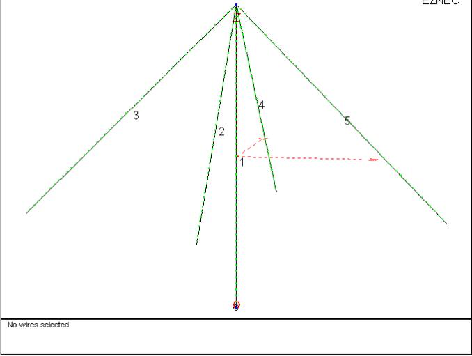
My rectangular arrays use elements with four 20 foot long #16 loading wires, insulated by fishing line used to support the wires. I terminate the guying 20 feet out from the base of the antenna. The entire structure is self-resonant on 80 meters. The large "hat" makes current essentially uniform throughout the vertical element while minimizing unwanted sensitivity to high angle radiation, and also supports the elements.
Eznec Download
Eznec RXvrhat
This
structure is base
loaded with a series
L/R
Each element requires a stable ground system. Ground loss is not important, but long and short term loss stability with climatic changes is very important. I use a minimum of four buried radials, each 1/8- to 1/4-wl long, on each element. Always place radials directly under each hat wire. Do NOT use small elevated radial systems or grossly non-symmetrical radial systems! Elevated radials will reduce VSWR bandwidth of the array, introducing unwanted phase shift. They also make the system susceptible to high angle signals, and are more susceptible to common-mode noise on feed lines and other conductors around the antenna than buried or earthed radials. It is not necessary to bury radials, but if the radials aren't buried multiple ground rods are a good idea. The feed line should also be buried or if laid on the ground "choked" with high permeability ferrite beads near each element.
feed line Length
Unlike transmitting arrays, it is not necessary to use odd-quarter wave lines. It might be a tiny bit better if you use exact multiples of 1/4 wl, but even 1/2 wl lines work perfectly fine. Multiples of 1/4 wl work better in cases where you might fail to match antenna impedances to the transmission lines correctly. The reason of this is that phase shift in a transmission line is independent of line SWR when the feed line is ANY multiple of 90-degrees. With ANY phasing system having standing waves on the feed line, you can properly feed the system by supplying equal currents to any feed line an even multiple of 1/2 wl. Any feed line having odd multiples of 1/4 wl requires equal voltages feeding the line. The phasing systems I use, unlike transmitting systems, are designed to supply either equal voltages or equal currents! The proper ratio adjustments are easily made. You will, however, have slightly less phase error if you use any multiple of 1/4 wl when the lines are mismatched.
Beware that foam cables are NOT .82 or any other standard velocity factor. They range from the .70 range up to around .92 in velocity factor, depending on the ratio of gas to material in the dielectric. Only solid dielectric cable are predictable without measuring the cable.
Tuning the Elements
After careful planning and selecting the type of array, you should install the elements and the array's internal feed lines. Each element must be evaluated with an antenna analyzer that measures resistance and reactance. Connect the analyzer at the element's feedpoint, and follow these steps:
1.) Using a two foot long or less jumper cable, measure the antenna without a loading coil. Check the resonance for predicted values. It should be within several percent of the modeled self-resonant frequency.
2.) Touch the shield of the feed line in the array to the case of the analyzer or the vertical's ground. If impedance changes more than five percent, you need a better ground system.
3.) Install the loading inductance predicted, and sweep the desired frequency range for lowest SWR and zero reactance. If your analyzer is working correctly the lowest SWR will be at zero reactance, or very close to that frequency.
4.) Fine tune the inductance to make the antenna resonant at the desired frequency. You do this by adding or removing small inductors in series with a main inductor, or by adding or removing turns. Fine adjustments can be made by squeezing or spreading turns on the main loading coil's form, if it is a toroid or non-potted construction.
5.) Add enough series resistance to bring antenna impedance to 75 ohms at resonance (assuming you use 75 ohm cables).
6.) Check the feedpoint again for stability by connecting and disconnecting the shield of the unused array transmission line from the case of the analyzer or the ground system connection point. Again it should remain within 5%, or you need to improve the ground. If you can not improve the ground, you will have to isolate the ground by using a choke balun on the feed line.
Once one element is tested and proven, you should be able to duplicate that element with near-perfect results. I remove the matching system and take it to the test bench, and find a series C/R combination that produces the same resonant frequency. Multiple networks can be constructed on the test bench, and then moved to each element. My elements normally fall within 20 kHz of each other, any large difference in impedance or resonant frequency is a sign of potential performance problems.
Here is the 75 ohm SWR plot of this element:
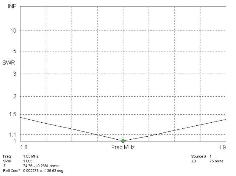
Bandwidth is excellent, and sensitivity (gain) including all losses is -13 dBi. This element is almost perfect for use in small receiving arrays, since signal level and bandwidth are very good. Because of the large amount of capacitance and the resistance loading, the element will not significantly change phase or sensitivity with frequency over the entire 160-meter band! In addition, it has very little response to high angle signals (and noise).
In circular arrays, hat wires can be extended to ~35 feet with only three loading wires used. My 350- foot diameter arrays position two loading wires (using tarred nylon fishing net string for insulation) in line with the perimeter of the antennas, while the third wire on each element is used to "pull out" from the array center. This tensions the perimeter wires and guys the entire structure. Even though hat wires are not spaced exactly 120 degrees apart, the effects on sensitivity to high angle signals are insignificant.
Arrays of Elements
Arrays of short verticals have both advantages and disadvantages compared to other antennas, such as Beverages and elongated loops. The comparison is:
| Elongated Loops | Beverages | Verticals and Wide-spaced Beverages | |
| Area required | small <3/8-wl | large >1-wl | 1/2- to 3-wl |
| Effort | modest | minimal | modest to large |
| Pattern | worse than 2-el vert, poorest | about same as 4-sq, middle | middle to best |
| Bandwidth | multiple bands | multiple bands | single/multiple band |
| Signal level | Low | Modest | Modest |
The primary advantage of arrays of short vertical arrays are excellent pattern and reasonable signal levels. Unlike balanced elongated loop systems, they are non-critical for feed line routing (other than keeping the feed line on the ground), matching transformers (transformers are not even required!), and earth conditions around the antenna. They have the same approximate output as simple Beverage arrays, and can still be made to work over very wide frequency ranges. The disadvantage is they are more complex, and require bandswitching to work on two bands.
Note: I am finishing the layout of an FET amplified array that will allow ten-foot non-hat verticals that work from VLF to 80-meters and above, with the same basic directional characteristics over that range without switching.
Broadside-Endfire Array
The most directive four-element antenna possible is a broadside-endfire array. I use 70 feet endfire spacing and 330-feet broadside spacing between endfire cells, and get a pattern like this:
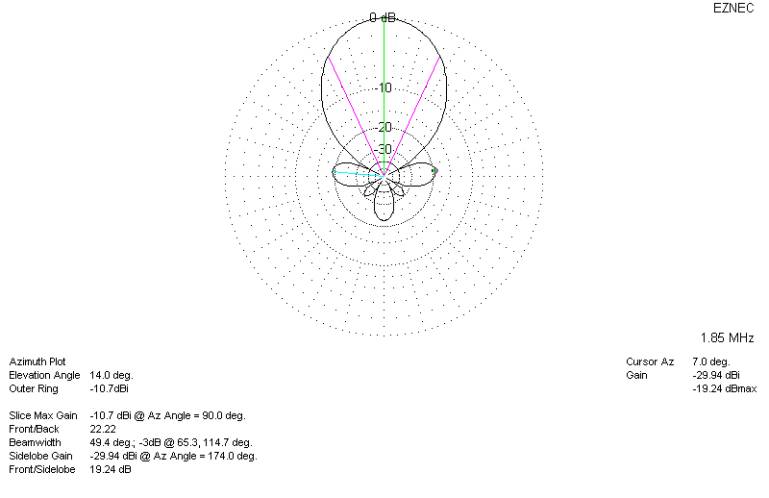
This array has an RDF of 13dB (two dB more than the large 4-square), and a HPBW of 47 degrees! The performance is similar to a circular array with eight elements in a 350-foot diameter circle, that allows directional selection every 45 degrees. The circular array uses techniques similar to the broadside-endfire, except the relay system is modified to switch eight antennas.
I've found that 1000 feet is about the maximum physical separation allowing signals to be reliably combined on 160-meters. Arrays occupying areas larger than 2 wavelengths have far too much random phase and amplitude shift, preventing reliable combining of signals.