Bandswitch wiring, especially wire connections to the wafers, must not have sharp points or protrusions. Solder connections should be smooth and rounded, the solder forming a small rounded ball that covers all sharp edges. The last motion in lead attachment to each contact should be soldering, not clipping! Clipping of protruding wires results in sharp edges at the cut point. Sharp edges concentrate the electric field in a small area. This greatly decreases voltage breakdown. The difference in voltage breakdown can be profound, more than 50% reduction in voltage breakdown may result from changing a rounded connection to a sharp point.
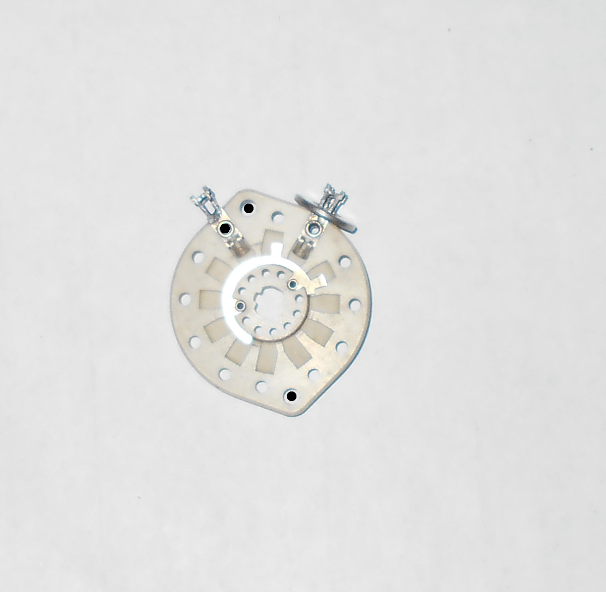
In some cases, and intentional anti-corona ring is added near the highest-voltage contacts. Any large smooth rounded metallic object connected to the contact will disperse the electric field and reduce voltage gradient between that contact and other nearby connection or hardware. This will greatly increase switch voltage hold-off. This picture shows the anti-corona washer used in the Ameritron AL80 series of amplifiers. This washer spreads the electric field out, increasing contact breakdown by about 50-70%!
Peak voltage between switch contacts and ground or other contacts is about
equal to the high voltage in normal operation. Voltage can be
several times the dc high voltage levels if an amoplifier is
mistuned, or if there is a momentary loss of load.
Contact Alignment
Switches normally have a detent located at the front of the switch. The detent causes the switch to "snap" into each band position, keeping the contacts centered.
The detent may consist of one or more balls held with spring pressure against a ball-race with recesses or dimples, or a spring-loaded cam follower that presses against a notched wheel attached to the shaft.
When the mounting nuts of supports are loosened, clearance in wafer holes and mounting brackets allows wafers to rotate a few degrees. This allows the contacts of each wafer rotor to be centered in the mating wafer stator contact. Pick-up-and-hold contacts are normally adjusted so they do not extend beyond the edge of the leading-edge stator contact.
Contact alignment is normally performed in the middle of active contacts selected by rotation, checking by rotating in from each direction for that particular wafer. For example if a particular band switch wafer covers 160-10 meters (six positions). The center position is selected, and the wafer mounting screws loosened. Each switch wafer contact group is centered or aligned, and the mounting screws retightened. After adjustment, each position of rotation should be checked for contact centering or alignment.
Dirt and dust are deleterious to voltage breakdown of components. They are most harmful under high humidity, when moisture and salts in the contaminant may increase conductivity. Contaminants mainly reduce voltage breakdown because they fill air gaps with slightly conductive particles.
Well-designed switches normally have much closer contact spacing than dielectric paths, because contact angles move the ends near the rotor close together. Even so, contamination of the (normally) ceramic dielectric can be an issue in conditions of severe dust buildup.
Never use contact cleaners or other lubricants on high-voltage high-current switches or relays. Many contact cleaners have carbon-based chemicals that will speed the formation of carbon tracks when corona or arcing forms. Other lubricants are very poor RF dielectrics, reducing voltage ratings.
Cleaners should be pure light hydrocarbons that fully evaporate, leaving no residual contaminants.