Amplifier tank circuit
The following is a model of an amplifier tank circuit with all parameters shown:
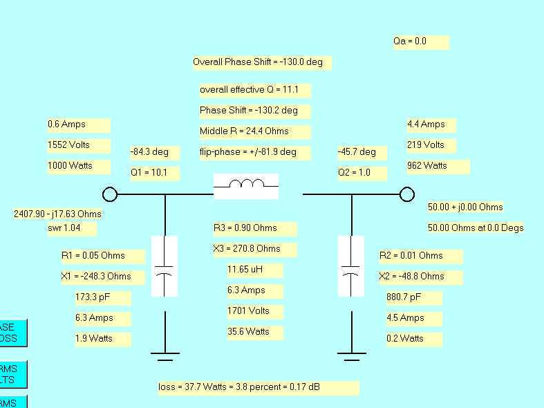
Notice the following:
Voltage across the tank coil exceeds input voltage
Current in capacitors exceeds input current
Phase shift across the inductor is -130 degrees
Increasing the loaded Q from ~11 to ~15 results in:
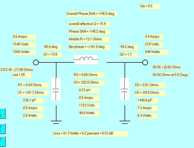
Notice the following:
- Voltage across the inductor increases
- Currents increase
- Loss increases
- Phase shift increases
Conclusions
(In all cases Q refers to loaded or operating Q)
- Voltage across the inductor is always more than tank input voltage
- Voltage increases with increasing Q
- Phase shift increases with increasing Q
- Currents increase with increasing Q
Voltages across a bandswitch contact can exceed tank input voltage, if the contact is near the input of the network. This, coupled with the high energy storage, can result in seemingly conservative components failing when the amplifier is lightly loaded for two reasons:
- Tank circuit operating Q is higher when the tank is lightly loaded
- The output device pumps the tank, and all of the energy may not be removed. This allows voltages at the input to greatly increase. See practical demonstration