If we objectively examine most tuning pulser (pecker), some ESSB discussions, and CW or amplifier forums, we find misconceptions about SSB and CW transmitters behavior. Understanding how the transmitter works, especially the RF generation process, goes hand-in-hand with adjusting amplifiers and designing RF equipment.
Discussions of SSB behavior also fit, in significant part, with AM and CW transmitters and amplifiers. As with SSB transmissions, AM and CW transmitters are amplitude modulated. This is why undistorted operation and maintaining original bandwidth of all three modes, CW, SSB, and AM, requires linear amplification on stages following the modulation process. Even off-on keyed CW requires linear amplification. AM and CW transmissions contain sidebands above and below a carrier frequency. SSB transmissions are missing the carrier and one group of sidebands, but still convey information through amplitude modulation.
Frequency Conversion View, the Simple Approach
SSB single tone
If we examine frequency domain of an ideal SSB transmitter, we find the SSB transmitter coverts or moves audio frequencies to much higher radio frequencies. In effect, the SSB transmitter moves the zero frequency point of audio up to radio frequencies. LSB (lower sideband) transmissions become inverted, with the lowest audio frequency highest in spectrum. LSB transmissions are the difference between audio frequencies and the suppressed radio frequency carrier. USB transmissions sum the audio to the suppressed carrier frequency.
If we modulate any HF SSB transmitter with a single tone, such as a 50 Hz tone, transmitter output contains no 50 Hz energy. If there was 50 Hz energy, it would not make it through the coupling components, including matching networks, filters, and antennas.
Let's look at an 80-meter band example. With "carrier" set at 3.800 MHz, a steady 50 Hz tone is applied to the balanced modulator (or digital equivalent of the balanced modulator). We now have three new frequencies:
- The carrier at 3.800 MHz
- The upper sideband, at 3.800 MHz plus .00005 MHz, resulting in 3.80005 MHz
- The lower sideband, at 3.800 MHz minus .00005 MHz, or 3.79995 MHz
Assuming we filter the DSB AM signal in a narrow LSB filter, or phase cancel the carrier and USB out, the result is a pure radio frequency sine wave at 3,799,950 Hz, or 3.79995 MHz. This is why the 50 Hz tone passes through antenna tuners, coax, and radiates from a 3.8 MHz dipole!
A 50Hz tone, from an ESSB transmitter, looks like this:
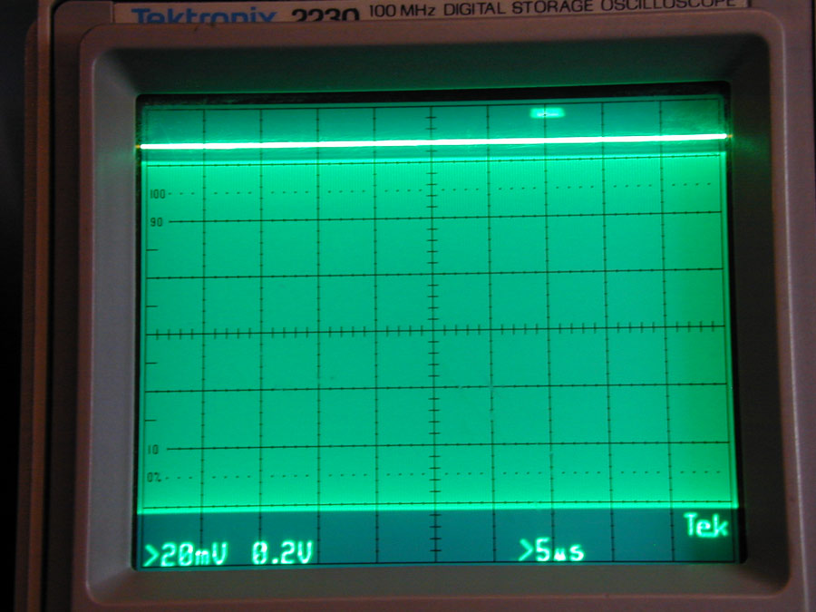
This is a sweep rate of 5uS per division, or 200,000 RF cycles per division. We see each horizontal division is full, meaning the applied frequency is much higher than 200 kHz.
Note there is no energy at all at 50 Hz. We have the equivalent of a 3.799,950 MHz steady CW carrier.
The single tone RF output, regardless of audio tone input frequency, is a single narrow RF spike that actually is a steady unmodulated RF carrier! This leads us to what a single tone signal is.
Audio Pulsed Tone equals CW OFF-ON Keyed Carrier
Years ago, Collins and other companies generated CW this way. Collins injected a "pure" 1000 Hz tone into the audio chain of the 32S1 SSB exciter and KWM-2 transceivers. This is because an audio tone is simply converted to a single radio frequency by the SSB system. Collins had to abandon that idea, because hum, noise, and distortion, as well as opposite sidebands and carrier, leaked out in levels sufficient to generate frequent complaints and FCC citations, but that was due to the physical transmitters being less-than-perfect.
Two-Tone
A two-tone source is used to simulate SSB performance. A two-tone test is a very marginal IM distortion test, because it varies load on power and bias supplies at the tone frequency separation rate. A two-tone test will not normally show power supply dynamic regulation issues or ALC problems, but a two-tone test is better than nothing. (A true distortion test would use either real speech, or three tones. With three tones, one would represent bass, one represent treble, and the third tone represent the syllabic rate of speech. Peak IMD levels would be captured over many sweeps and displayed.)
Let's consider tones of 50 Hz and 2500 Hz. A 3.800 MHz LSB transmitter would now output two frequencies, 3.799,950 MHz for the 50 Hz tone, and 3.797,500 MHz for the 2500 Hz LSB tone.
The resulting waveform is a two-tone signal:
Notice zeros are reached about every 0.41 milliseconds. This corresponds to 2500 Hz - 50 Hz = 2450 Hz. The actual RF signal never gets below 80 meters, and never presents audio frequencies to amplifiers, antennas, or anything else. Audio frequencies will only appear after the signal is detected!
If we trace the outline of crests above zero in a two-tone test, we would draw a humped waveform. The waveform would be the same as an unfiltered full-wave rectifier dc output. In normal class AB or B amplifiers, the traced waveform would load power supplies at that rate, and tend to force current back into bias supplies at that same rate. This waveform is always at the difference between RF frequencies. In this case a 50 and 2500 Hz tone would load power supplies and back feed bias supplies at a 2450 Hz rate. Neither the 50 Hz or 2500 Hz, or any two original tones, appears at the supplies!