What_Causes_Clicks?


|
What_Causes_Clicks?
|
|
Bandwidth rules Part 97.307
Clicks are often a problem on congested bands, yet with modern radios they don't need to be a problem. In the past, engineers and designers didn't have the easy ability to generate filtered waveforms. Radios lacked wide 2-3 kHz wide SSB filters, let alone narrow 250-500Hz filters. Op-amps were unheard of, and L-C filters were large, bulky and expensive. Today, every radio manufactured has the ability to be very clean. Modern RadiosMost modern radios include 500Hz and narrower receiver filters that operate at the same IF frequency as their transmitter section. Transmitted signals are often routed through the SSB filters with intentional TX switching, when they could just as easily be routed through CW filters! We will see later in this page that TX signals could be routed through CW filters to eliminate sidebands, yet manufacturers foolishly use the SSB filters. If you examine the bandwidth of a FT1000-series radio, you will find the clicks disappear at the BW limits of the SSB filter. This is because they run an essentially unshaped CW signal through the SSB filter, and that filter sets the bandwidth of clicks. The sad thing is once you listen to that signal through a 500Hz filter, it sounds absolutely no different ON FREQUENCY than it would if it were nearly click free. The only people who can notice the difference between a clicking rig and a clean rig are the people operating on adjacent frequencies! Claims that certain shapes produce certain "bell sounds" or high readability are not correct, they are certainly not based on engineering or actual blind A-B tests. If you examine the audio output of your radio with a 500Hz filter in use, you will see ANY waveshape transmitter has the same nearly raised-sine (Gauss or Bell curve) shape output to your ear! That includes wide signals and narrow ones. The speed limit you can copy with a 500Hz filter is the same limit you can transmit with. It makes no difference what end of the path the filter is on, or if there is one at both ends, so far as speed is concerned! (This assumes the filters have reasonably good and easy to achieve group-delay characteristics.) We hear a few mS rise, no matter if it is a sine shape or a square, as a "tick". For demonstration, listen to the pure sine wave on WWV that "tics" every second! What Could Be DoneAt no cost to manufacturers, they could build a click free radio. Every component is in the radio, the problem all centers around poor or careless engineering. Amplifier stages are reasonably linear (so they can amplify SSB), and virtually every radio contains power control circuitry that could be easily modified to provide wave-shaping. Even without wave-shaping, the transmitter could process transmitted CW though a 250Hz or 500Hz filter. Sadly, most of the commonly used radios have as bad or worse keying characteristics than old rigs. It's as if the manufactures either don't understand CW, or don't care. The result is we are left with a mess, because many top-of-the-line and very popular rigs have horrible keying sidebands. On frequency with normal CW filters, we would not be able to tell any difference between the sound of a clicking radio and one that is clean! There is no justification or reason for radios to be 3kHz wide on CW. How to Identify Click ProblemsWe hardly notice clicks, and we certainly can not tell a clean rig from a dirty rig, when we are listening right on the CW station's frequency! Even an scope won't tell us much about signal bandwidth, or if the rig has excessive clicks. In order to check clicks, we must:
If we do not follow those three guidelines, we can't tell if a rig is clean or not. If you are testing your own rig, your second receiver must have a narrow filter and be coupled to the rig-under-test through a proper attenuator. Why Worry About Clicks?Clicks are most problematic when we try to copy weak signals next to moderately strong signals. If you only operate on empty bands, run low power, and never operate within four or five kHz of weak stations, bandwidth is probably not a concern. If we contest, work DX, or Ragchew near other QSO's, and especially when we run more than a few hundred watts and have large antennas, we should be mindful of our bandwidth. If you listen to a recording of a clicking radio, you can hear how devastating clicks are to nearby weaker signals. This signal is from Europe on 40 meters, and it is daylight over half of the path!! For a mathematical tutorial on clicks, visit W9CF's site. Kevin's analysis deals with bandwidth requirements related ONLY to modulation of the envelope. I'll explain the same thing in verbal form, as I discuss sidebands created by rise and fall times. CW keying is really just 100% AM modulation, as you will see! There are several INCORRECT but popular misconceptions. They are:
What Causes Clicks?While a fast rise and fall time guarantee excessive bandwidth, a long rise and fall is no guarantee a radio will be "click-free". Some radios switch into transmit while the synthesizer (VCO) circuits are still settling to a new frequency. An IC-775DSP I owned was particularly bad about this, and also had VCO leakage problems. The amount of garbage varied with how I used the radio, including "VFO" frequency settings of unused VFO's! Radios with VCO or synthesizer settling time problems generally produce a loud "thump" on key closure on the second VCO frequency. That thump will be right on the DX station when the operator is working split. If you listen in pileups, you will hear a small percentage of rigs with this problem. If the operator uses QSK, VCO-switching-thumps can be particularly annoying. Thumps will occur every time the VCO moves from the receive frequency to the transmit frequency, sounding like a leading-edge click! Rise and fall times are also important. A long rise and fall time does not always result in narrow CW transmitter bandwidth, even though a faster-than-needed rise and fall time almost certainly results in excessive bandwidth. Many radios have rise and fall times that are much too fast. How fast is much too fast? For now let's ignore VCO switching problems, and consider envelope shape. Rise and FallThe ARRL recommends a 5 mS rise and 5 mS fall time for CW, based on data in section 2.202 of FCC rules and CCIR Radio regulations. According to professional sources, a 5 ms rise and fall time is not harmful to readability at 35 wpm under marginal (fading) conditions, and 60 wpm when signals are reasonably above noise floor. This rise and fall results in a occupied bandwidth of 150 Hz, although unwanted transient energy caused by the shape of the waveform slope may appear at wider bandwidths. What Limits Bandwidth?When determining bandwidth of a stable signal (no oscillator problems), two things come into play in.
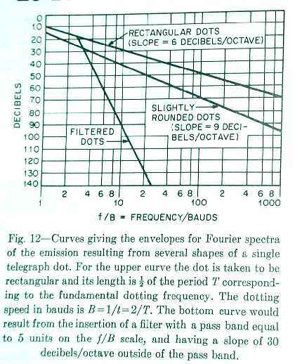
The slope (bandwidth) and the amount of change in a sloped area (level) combine to determine how offensive the transmitted signal is. Very subtle changes in envelope shape have a profound effect on key click amplitude and frequency dispersion. This makes it nearly impossible to tell if our radios are as clean as they could be by looking at envelope shape. We can be certain sharp transitions will cause problems, especially if we can actually see them on a oscilloscope. We can also be sure that a rise and fall faster than 2 or 3 milliseconds will cause a bandwidth problem. Reference Data for Radio Engineers, in the section of Radio Noise and Interference, addresses key clicks in a manner the ARRL Handbook does not. They give an example of multi-pole shaping of waveform. The ARRL Handbook seems stuck with the incorrect notion that a single-pole R/C filter provides proper shaping, something doubtless left over from 1940's technology when better filters were expensive, large, and complicated. Here are the bandwidth curves of three basic envelope shapes, one rectangular (some radios are this bad!), one for a proper single pole R/C filter with slightly rounded shape (The ARRL suggests this shape. Probably because it was practical in the early years and "stuck" even though it is not ideal), and one for a filtered rise and fall (this would be a sine-shaped rise and fall from a multi-pole filter). We can clearly see a large difference in bandwidth in the curves below:
From Ref Data for Radio Engineers 29-10 1977 Edition Most radios, through poor design, fit in the rectangular to slightly-rounded category! How Can I Fix My Radio?Some radios are easy to cure because others have done the work for you. If you are looking for a cure for a unique radio you first have to understand exactly how the keying system in your radio functions. To have a clean signal, the following processes must occur in exact order:
Tracking all this down is lengthy, and requires a dual trace scope and "dit" generator. Things that can prevent this are:
What Can Manufacturers Do?Radio manufacturers can certainly do a great deal more than they are. First, they created the problems through poor engineering and design. Why are we stuck fixing them? Did they take our money and run? All of the parts are there to make radios virtually click-free, yet the only manufacturer who has taken an active interest in this (and who seems to care at all about our signal quality and frequency usage) is Ten-Tec! To date I haven't found any other manufacturer admitting a problem, or even offering technical support for bandwidth problems. Let me give an example of what could be done with current radios: Virtually every radio contains a CW filter that operates at the IF frequency of the transmitter, yet nearly every radio transmits CW through the SSB filter! Engineers actually added circuitry and parts, in many cases, to steer the CW through the wider filter on transmit! If you listen to radios, in particular the FT1000-series, you will notice they have an ultimate click-bandwidth of about the same width as the SSB filter. That's because the poorly-shaped CW waveform with excessively fast rise-and-fall is filtered through the SSB filter. If these same radios immediately turned on the output stages, and held them on for several mS after the key line was opened, they could send perfect filtered CW through the CW filter. A 500Hz filter would cause a steep roll-off in clicks, even if driven by a relatively "square" and very broad CW signal. The resulting waveform would be a slightly modified raised-sine envelope. The listener would not be able to tell any difference between the ON FREQUENCY sound of a 500Hz CW-filtered transmitter and an unfiltered signal with excessive bandwidth, if he used a 500Hz or narrower filter in his receiver! As a matter of fact, I normally transmit through a 250Hz filter in my FT1000D, rather than the 2.4kHz SSB filter Yaesu selected. No one listening on frequency, even DX stations copying my signal near noise level, can tell the difference when I select 2.4KHz or 250Hz bandwidth! The only place transmitter filtering makes a difference is up or down the band from my operating frequency. This is why we can not tell whether a signal has a proper rise and fall time, sharp level transitions, or any other envelope shape problem when we listen to the actual CW tones through a 500Hz filter. Even a very fast rise-time, with a spiked rise and fall, sounds good (and even looks perfect on a scope connected after the receiver's narrow filter)! Claim's that a certain shape rise and fall produce a "pleasing-sound" are not true at all. First, our ears can't identify a sound only 5mS long, and second...the receiver's CW filter (assuming it is under several hundred Hz BW) reshapes the waveform to a proper rise and fall! Why is any of this our concern? Why do we have to work on radios, and suffer with clicks? Certainly not because of a cost issue! All the parts are in the radios. It is a simple lack of good design-engineering, most likely driven by a lack of concern by manufacturers for providing rigs with good signal quality. What Can We Do?First, we can let manufacturers know it is their problem. Let's ask the ARRL to publish useful reviews with bandwidth pictures showing a spectral display of CW (and SSB) bandwidth. Let's ask them to check for VCO problems, and publish any abnormalities. Let's rate radios as poor, fair, good, or excellent so readers don't have to be EE's to understand what they are buying (and using). Radios are too expensive, too difficult to work on, and last too long for us to ignore this problem. We need to stop these problems at the design phase, instead of out in the field. |