My ADSL Modem Filter
Around 2005, I changed from ISDN to satellite. Both ISDN and satellite were interference free.
Around 2008, I switched from Satellite to ADSL. ADSL uses carriers up to 1 MHz for data to the house. Since my ADSL circuit is about 50,000 feet long, signal levels are very low. My 160-meter signals would drop ADSL service at just 50-100 watts.
Part of the correction was a new better modem, which is a 2Wire brand modem. I also needed a good ADSL modem filter, and none were available.
Most filters on the Internet do not properly terminate the telephone line. This is because Chebyshev filters, although having a desirable rapid roll-off above cutoff, are mismatched from the normal 100-ohm surge impedance throughout the passband. This mismatch causes passband ripple, as well as input impedance ripples. Because of this, they can induce excessive tilt to broad bandwidth ADSL signals. This can hurt ADSL speed, because some carriers can lose S/N ratio. Most public domain ADSL filters load the line heavily at 300-800 kHz, some with as low as 25 ohms, resulting in loss of ADSL carrier levels in that range. This also causes standing waves on the telephone lines, although I'm not sure how detrimental it is in most system. My own ADSL system dropped from 1.5mbps to about 900kbps when using a Chebyshev filter.
I modified a Butterworth filter by tuning input inductors, and adding pre-modem 160 meter traps.
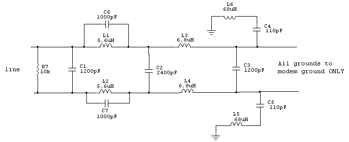
All capacitors are 500 volt or higher, and all chokes are axial lead 50-250 mA rated components. Omit R7, or use a very high leak value (>500K).
My design goal was to make the filter:
- Transparent to ADSL mode impedance, conforming to Telco line impedance standards
- Off-the-shelf standard component values, no hand-winding and unpredictable results
- High isolation levels in both common mode and differential mode
- Through use of small components, an improvement in lightning immunity. Better to have filter components fail, than an expensive modem
SPICE Model ADSL Filters
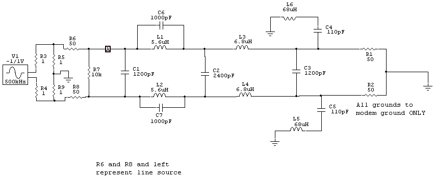
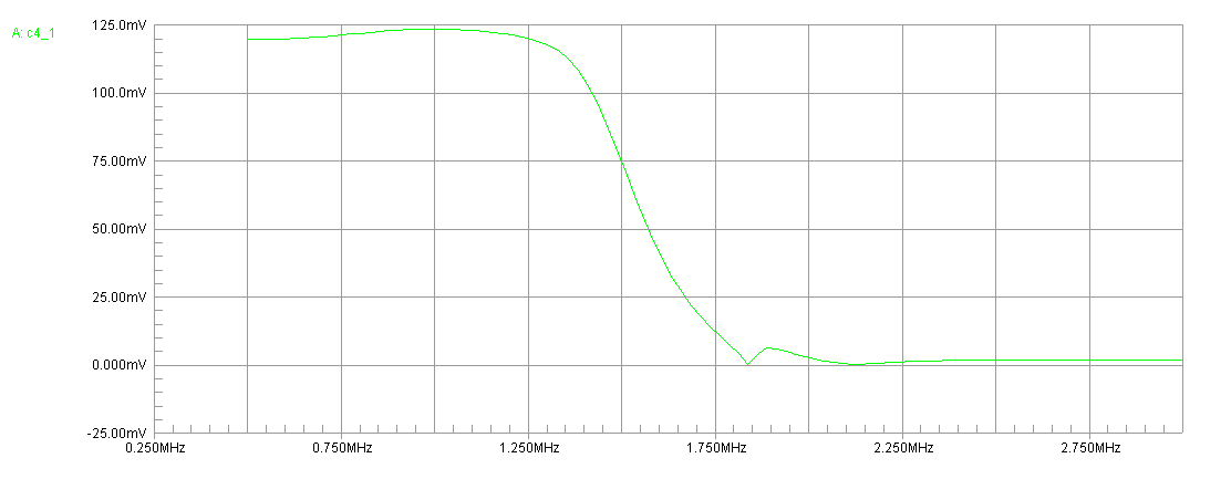
At point A, we have the following swept voltage:
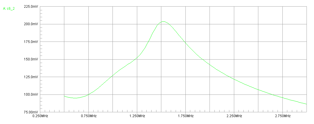
The flatter this voltage sweep below 1.1 MHz, the flatter filter input impedance for Telco lines. The strong peak at 1.5 MHz is well above DSL frequencies, and is the result of input traps decoupling the filter input from the line.
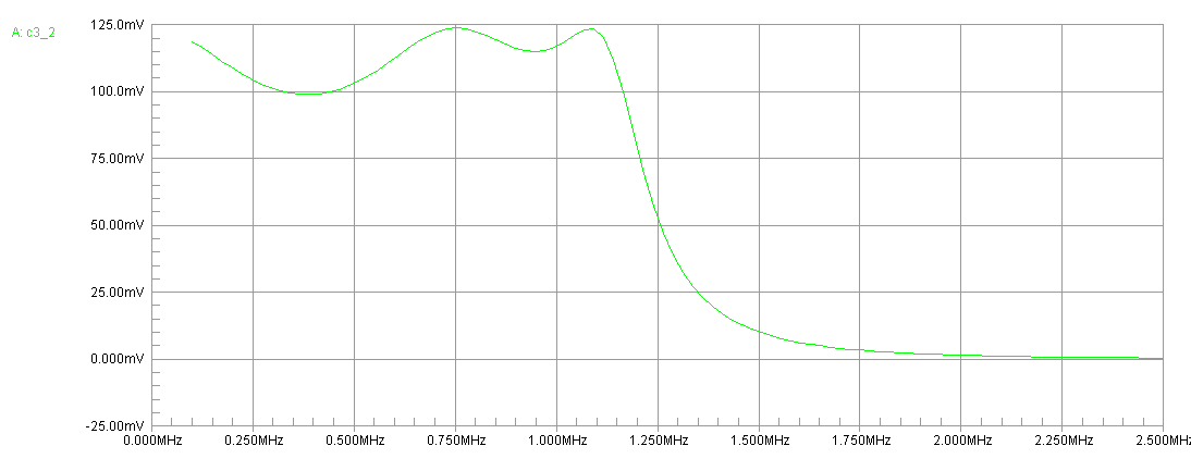
Compare the above to another Internet design. This sweep shows improper Telco line termination caused by using a fast roll-off filter:
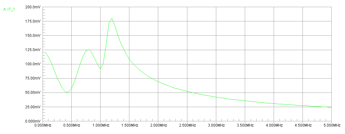
Note with a 100-ohm source, input impedance is so low voltage drops to 50 mV.
ADSL Filter Attenuation
W8JI ADSL
This filter is nearly flat down to audio. It has high common mode rejection, as well as differential mode, although severe cases of common mode are best handled by a supplemental broadband common mode filter.
Other Typical ADSL Filter
This filter has ripple in passband, but is flat above passband. It also does not have nearly the same common mode isolation on 160 meters.
Common Mode Filtering or Suppression
Common mode is best handled by a special common mode filter. Common mode impedance should be equivalent to a very high series loss resistance. This dictates use of very high µ materials. Proper materials would have a high loss tangent compared to inductance over the frequency range of interest. This would be certain 30 materials, 60 materials, or 70 materials.
31 Material, for example, has a magnetic permeability of about 1000 on 160 meters, decreasing to 300 on 30 meters. It has a Q of 1 around 80 meters. It is best for suppression above 4 MHz, because a choke wound on this core material is unlikely to "series tune" the external system's common mode impedance and increase current.
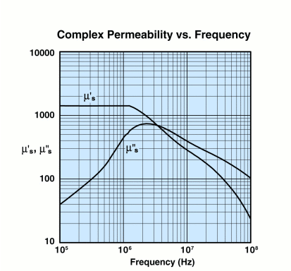
In this case, losses dominate above 4 MHz.
Although generally not described as an HF suppression material, 77 material or materials similar to 77 offer superior suppression below 4 MHz :
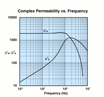
77 material losses dominate above 2 MHz.
Many or most materials in the 70's offer superior suppression on lower HF without compromising higher HF frequencies. This material is generally better than 31 above 10 MHz because the choke's impedance appears as an almost pure resistance. A resistance cannot resonate with the external system's common mode impedance.
I use short Telco jumper cables to wind common mode filters.