The EBS 1, or other bias circuits, are sometimes damaged by tube flashovers. Unfortunately there is no way to prevent such damage, because peak voltages can exceed hundreds of volts while currents reach dozens of amperes. Sometimes MOV's will help, as will higher value filament bypass capacitors on the filament choke, but ultimately, it is impossible to 100% protect against all tube faults.
Fortunately, it is pretty easy to repair the bias system.
Repairing Bias Systems
Before any repair is made, it is important to correct the cause of failure. Almost exclusively, the problem is a tube flashing over. Sometimes this happens once, and never repeats. One common cause of flashover is running a tube too cold, so the getter never properly functions. Never run an external anode tube at reduced filament voltage, because external anode tubes getter from cathode heat. Internal anode tubes usually getter from anode heat, so occasionally the anode should be brought to proper operating temperatures. Tube data sheets will advise on proper operating ranges.
Be sure your amplifier has a proper fault-current limiting resistor. The AL80B mainframe now uses two 10-ohm 10-watt pulse rated resistors. The AL12 series mainframe uses a large single resistor of about 20 ohms. There are also 65-volt MOV clamps added to the "cold" side of the filament chokes. At a minimum I would upgrade any amplifier to current production. If it is a different brand, I would add the same protection Ameritron uses.
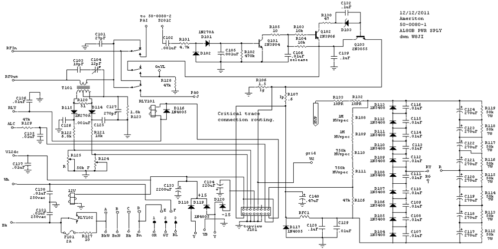
If a tube is repeatedly arcing, it is a sign the tube is developing gas. The tube should be replaced. The following is the AL80B schematic, showing R132 and R133, which are fault current limiting resistors. MOV's are on the transformer side of the filament supply, and are not on this board.
The circuit below is the bias section. Note additional diode D4. If you want additional protection, sacrificial protection diode D4 can be added. D4 should be at or just above the cutoff bias of the tube. While not generally necessary, it will not hurt to parallel D4 with a resistor, like a 4.7k 1-watt MOX. R7 is external in EBS-1.
To test the above circuit, replace V2 with a 24 volt or higher supply through R99. Make R99 a 22-ohm 25-watt resistor. If you use a clamp diode, be sure the diode's dissipation is not exceeded by current from the supply though R99. A one-ampere or larger dc supply will work as a test supply.
Forward bias can be added to turn the switch on. Apply at least 5 volts through a 100k resistor to either end of R1. You should have the following approximate voltages:
| Measure point | Q1 base high | fail problem | Q1 base low | fail problem |
| R5,R3 | <2 volts | shorted or open D1 and D2, open Q1 | Same as C3, at tube cutoff | any transistor shorted |
| D3,R8 | at operating bias voltage | Q1 open, Q2 open, D3 short, Q3 short | 0 volts | Q1 or Q2 short |
| Q3 base | 0.5 to 1 volt | Q1, Q2 open, D3 open, Q3 short | 0 volts | R7 path open, Q3 fail |