This page is under modification, is not complete at present, and will eventually be split into linear loading and counterpoise pages. I tried to model the FCP under a 45-50 foot high inverted L. My thinking was by varying height we could see if the FCP divorced earth from the counterpoise as proposed. That didn't work out well, I found any sparse or truncated radial system allowed radiation from the horizontal wire section at very high angles. When I move the L antenna and radial system up above earth, the system starts to act like a low dipole and have very strong radiation from the flattop. This makes efficiency look dramatically better in short or sparse radial systems with increased height above earth, but the bulk of "new" EM energy is at very high angles. My next efforts will be repeating the models and comparing estimated field strength at lower angles. See table at end.
While the only indisputable proof of performance come from actual field strength comparisons between a known working reference and a system under evaluation, models are very accurate. We must include everything influencing the antenna, and understand simple models treat earth as a homogeneous media. Even if a model does not perfectly represent earth and surrounding structures, models can still provide a useful "feel" for systems behavior.
The most frequent modeling errors are:
Not including feed lines, or analyzing the interaction of feed lines
Not considering matching system losses
Failure to recognize models can use perfect, ground-independent, sources
| Antenna Inverted L 50 feet high | 2:1 Bandwidth + - kHz | Max. Gain dBi | Feedpoint impedance ohms | common point radial voltage @ 1500 W |
| 60 radials 100-ft long | 25 | .71 | 19.8 | 58 |
| Four T** radials 80-ft long | 24 | 0.21 | 16 | 121 |
| Loaded four radials 80-ft long | 22 | -0.05 | 18.5 | 177 |
| 50 radials 50-ft long | 30 | -0.06 | 26.3 | 154 |
| Single folded x 4 radials 80-ft long | 20 | -0.11 | 18.6 | 321 |
| 15 radials 50-ft long | 30 | -0.2 | 29.5 | 410 |
| "FCP" system 33ft each side | 18 | -0.9 | 29.13 | 2400 |
| Loaded one radial 80-ft long | 18 | -1.76 | 21 | 143 |
| Single T** radial 80-ft long, 66ft total width outside termination end | -2.25 | 24.3 | 552 | |
Notes: *Unless noted, all power levels set at 1500 watts.
**"T" radials are single wires running out to a terminating wire, just like a regular T antenna but laid flat and used as a radial.
When evaluation new ideas or new systems, there are definite clues to abnormal behavior. A few common warning signs are:
1.) Only very specific feed line coupling systems can be used. Other commonly used or reasonably common methods fail, without logical technical explanation of why other common methods won't work.
2.) Claims are made models will not work, while reliable or meaningful A-B comparisons refuting model accuracy are missing. The common claim is "models will not work with this antenna".
3.) Performance verifications are either comparisons of grossly dissimilar systems (such as different polarization or antenna types), or Gotham standard reports. How much DX we worked, or far we worked, is not a verification of performance. I have worked Europe, Australia, and Asia on 160 meters from my mobile, and my 160 mobile antenna is less than 1% efficient.
4.) Comparisons are made only to less-than-ideal, or highly variable, systems. For example, a known mediocre performance system might be used to verify another antenna. A reference antenna must be a known, consistent, reliable, performer. My 160 meter mobile antenna, even though less than 1% efficient, ties or beats some large home-station antennas.
One way to evaluate counterpoise resonance is by installing a known electrical length Marconi antenna above the counterpoise. Here is a resonant 160-meter vertical over infinite perfect ground (note: current at 1 amp in source tables):
| EZNEC+ ver. 5.0 1/4 wave vertical perfect gnd 7/31/2012 8:59:56 AM --------------- SOURCE DATA --------------- Frequency = 1.83 MHz Source 1 Voltage = 37.9 V at 0.24 deg. Current = 1 A at 0.0 deg. Impedance = 37.89 + J 0.1565 ohms Power = 37.89 watts SWR (50 ohm system) = 1.319 (37.9 ohm system) = 1.004 |
The ~1830 kHz resonant Marconi #16AWG antenna is 131.2 feet tall.
We can test the electrical characteristics of a counterpoise by using the 131.2ft long Marconi antenna without any change in radiating element length. If we place it over a ground system that is resonant, the resonate frequency of the system should remain the same. Over the ground system described as a "K2AV FCP" (folded counterpoise) we learn:
| EZNEC+ ver. 5.0 FCP 1/4wl vert 7/31/2012 9:26:31 AM --------------- SOURCE DATA --------------- Frequency = 1.83 MHz Source 1 Voltage = 198.5 V at -80.01 deg. Current = 1 A at 0.0 deg. Impedance = 34.45 - J 195.5 ohms Power = 34.45 watts SWR (50 ohm system) = 24.290 (34.45 ohm system) = 34.177 |
We now have ~195 ohms of capacitive reactance at the feedpoint. Clearly, the counterpoise is not resonate.
With this in mind, we need to ask ourselves, "What causes the entire system to be resonant, if the counterpoise is not resonant?"
Let's look at the "isolation transformer", that (according to information in articles) cannot be replaced by anything else.
It is difficult to predict the exact effect of this transformer without measurement, because irons cores similar to the -2 series red cores have considerable flux leakage. Contrary to Handbooks, they do not "self-shield". As a matter of fact, inductance can vary by a ratio of 2:1 with the same number of turns spread evenly over a core, compared to the same winding compressed in a compact core area. In many of my RF designs, when -2 mix irons are used, stages are tuned by spreading or squeezing turns!
It has 20 turns on a T-300A2 core. This should be, with very tight evenly-spaced turns, about +j115 ohms reactance per winding. This would normally be a terrible coupling transformer, unless the load had considerable capacitive reactance. Use of this transformer strongly supports the 1/4λ vertical wire test model, which indicates the counterpoise is actually resonant far above the 160-meter band. The isolation transformer effectively adds about +j100 ohms in series with the 50 ohm feed line, and the antenna feedpoint. The exact contribution would vary greatly from mutual coupling between windings on the much less-than-perfect "leaky core".
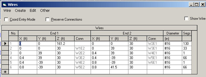
Moving the counterpoise to 1830 kHz, with 4.8 inch spacing and no dielectric, required the following wire table:
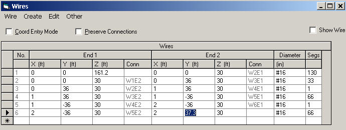
After extending the counterpoise from 33 feet "radius" to 39 feet "radius", I adjusted the open end of wire 6 for exact resonance. This gave the following impedance with a 131.2 foot long radiator (note: at 1 ampere base current):
| EZNEC+ ver. 5.0 SW FCP 7/31/2012 1:18:26 PM --------------- SOURCE DATA --------------- Frequency = 1.83 MHz Source 1 Voltage = 39.56 V at -0.17 deg. Current = 1 A at 0.0 deg. Impedance = 39.55 - J 0.1145 ohms Power = 39.55 watts SWR (50 ohm system) = 1.264 (39.5 ohm system) = 1.003 |
For best performance and lowest common mode on the feeder, anyone installing a folded loading system should tune the system in place. The general trend of folded loading is closer wire spacing requires a longer conductor. Closer-spacing generally increases loading loss, reduces bandwidth, and requires a longer conductor for the same resonant frequency.
Wider spacing decreases counterpoise loss, increases bandwidth, and requires less wire length for resonance.
This is the impedance at 1-foot spacing, and the wire table for one-foot wire spacing:
| EZNEC+ ver. 5.0 FCP 7/31/2012 1:28:28 PM --------------- SOURCE DATA --------------- Frequency = 1.83 MHz Source 1 Voltage = 38.1 V at -0.36 deg. Current = 1 A at 0.0 deg. Impedance = 38.09 - J 0.2403 ohms Power = 38.09 watts SWR (50 ohm system) = 1.313 (38.1 ohm system) = 1.006 |
Feed impedance resistive value decreased by 1.5 ohms with wider spacing, which indicates less counterpoise loss. Impedance is a valid test in this case, because only counterpoise spacing changed significantly, and the counterpoise was well-above (30 feet above) lossless earth. The new wire table is:
Counterpoises can be measured for resonance. This is best accomplished by using TWO identical counterpoises, in this case with them positioned at right angles, and measuring the counterpoises as we would a dipole. This will give a reasonable estimate of counterpoise resonance.
We can clearly see the systems being promoted today are not even close to resonant. The effect of non-resonance is not necessarily additional loss. The main effect of non-resonance is change of feedpoint impedance, and an increase in voltage between the counterpoise feed terminal and earth. Counterpoises not occupying significant wavelength area, and sparse in radial conductors (less than 15-30 conductors or less than .15-.2λ long) should be isolated from earth paths. This effect, which directly relates to counterpoise-to-earth voltage at and near the feedpoint, is aggravated when a counterpoise is non-resonant.
| EZNEC+ ver. 5.0 one T radials 7/30/2012 11:59:05 PM --------------- SOURCE DATA --------------- Frequency = 1.83 MHz Source 1 Voltage = 190.9 V at 0.16 deg. Current = 7.858 A at 0.0 deg. Impedance = 24.29 + J 0.06877 ohms Power = 1500 watts SWR (50 ohm system) = 2.058 (24.3 ohm system) = 1.003 |
| EZNEC+ ver. 5.0 4x T radials 7/31/2012 12:19:22 AM --------------- SOURCE DATA --------------- Frequency = 1.83 MHz Source 1 Voltage = 154.9 V at -2.63 deg. Current = 9.696 A at 0.0 deg. Impedance = 15.95 - J 0.7327 ohms Power = 1500 watts SWR (50 ohm system) = 3.135 (16 ohm system) = 1.047 |

| EZNEC+ ver. 5.0 Inv L 60 x 100ft radials 7/30/2012 9:49:54 PM --------------- SOURCE DATA --------------- Frequency = 1.83 MHz Source 1 Voltage = 172.3 V at 2.2 deg. Current = 8.713 A at 0.0 deg. Impedance = 19.76 + J 0.7595 ohms Power = 1500 watts SWR (50 ohm system) = 2.532 (19.76 ohm system) = 1.039 |

2:1 SWR Bandwidth + - 25 kHz
Gain .71 dBi
19.76 ohms
58 volts radial CP to ground
| EZNEC+ ver. 5.0 Inv L 50 x 50ft radials 7/30/2012 4:43:45 PM --------------- SOURCE DATA --------------- Frequency = 1.83 MHz Source 1 Voltage = 198.8 V at 0.8 deg. Current = 7.546 A at 0.0 deg. Impedance = 26.34 + J 0.369 ohms Power = 1500 watts SWR (50 ohm system) = 1.898 (26.3 ohm system) = 1.014 |
2:1 SWR Bandwidth + - 30 kHz
Gain -0.06 dBi
26.3 ohms
154 volts radial CP to ground
2:1 SWR Bandwidth + - 30 kHz
Gain -0.2 dBi
29.5 ohms
410 volts radial CP to ground
This antenna has one radial of #16 wires spaced 1-foot. To be resonant in folded configurations, the radial has to be 80 feet long. Inductor Q is about 220. This is a mediocre inductor, typical of #16 wire on a PVC form. To do a direct comparison to a folded counterpoise, the resonant single-fold counterpoise was modified to short both ends, and a loading inductor added.
| EZNEC+ ver. 5.0 one resonant coil radial 7/30/2012 10:52:25 PM --------------- SOURCE DATA --------------- Frequency = 1.83 MHz Source 1 Voltage = 177.4 V at 0.77 deg. Current = 8.454 A at 0.0 deg. Impedance = 20.99 + J 0.2804 ohms Power = 1500 watts SWR (50 ohm system) = 2.382 (21 ohm system) = 1.013 |
2:1 SWR Bandwidth + - 18 kHz
Gain -1.76 dBi
21 ohms
143 volts radial CP to ground
| EZNEC+ ver. 5.0 coil loaded radials x4 7/30/2012 11:07:21 PM --------------- SOURCE DATA --------------- Frequency = 1.83 MHz Source 1 Voltage = 166.5 V at 0.74 deg. Current = 9.011 A at 0.0 deg. Impedance = 18.47 + J 0.2388 ohms Power = 1500 watts SWR (50 ohm system) = 2.707 (18.5 ohm system) = 1.013 |

2:1 SWR Bandwidth + - 22 kHz
Gain -.05 dBi
18.5 ohms
177 volts radial CP to ground
This is a single counterpoise model of an FCP system, with the base 45-feet high above average soil. The antenna is the same basic 42-foot vertical section Inverted L used in other models. This is slightly different than described on Internet, because close spacing causes a guideline error warning in model. If wire spacing is too close, a modeling rule violation warning appears. This is the closest allowed spacing.
The effect of slightly wider fold spacing is a small downward shift in counterpoise resonant frequency.
Same antenna 8-feet high, L trimmed to resonance:
| EZNEC+ ver. 5.0 FCP 8ft 8/8/2012 6:41:46 PM --------------- SOURCE DATA --------------- Frequency = 1.83 MHz Source 1 Voltage = 209.1 V at 1.05 deg. Current = 7.176 A at 0.0 deg. Impedance = 29.13 + J 0.5349 ohms Power = 1500 watts SWR (50 ohm system) = 1.717 (29.2 ohm system) = 1.019 |

2:1 SWR Bandwidth + - 18 kHz
Gain -0.9 dBi
29.13 ohms
2400 volts radial CP to ground
(efficiency 26.2%)
Same FCP antenna at 8 feet, with L horizontal at right angles to FCP:
This antenna has four counterpoises made from #16 wires spaced 1-foot. To make radials self-resonant in single folded configurations, each radial has to be 80-feet long. This is about 160-ft of wire in each radial. This is normal behavior of folded wires. If radials contain only 1/4λ of total wire length, they will not be resonant inside the band.
| EZNEC+ ver. 5.0 folded radials 7/30/2012 10:32:15 PM --------------- SOURCE DATA --------------- Frequency = 1.83 MHz Source 1 Voltage = 167.1 V at -1.47 deg. Current = 8.978 A at 0.0 deg. Impedance = 18.61 - J 0.4779 ohms Power = 1500 watts SWR (50 ohm system) = 2.687 (18.6 ohm system) = 1.026 |
2:1 SWR Bandwidth + - 20 kHz
Gain -0.11 dBi
18.6 ohms
321 volts radial CP to ground
| Antenna Inverted L 50 feet high | 2:1 Bandwidth + - kHz | Gain dBi | Impedance ohms | common point radial voltage | Eff at 8 feet above earth | Eff at 45 feet above earth | ||
| 60 radials 100-ft long | 25 | .71 | 19.8 | 58 | 36.8% | 39.1% | ||
| Loaded four radials 80-ft long | 22 | -0.05 | 18.5 | 177 | 32.4% | 40.4% | ||
| 50 radials 50-ft long | 30 | -0.06 | 26.3 | 154 | 30.8% | 45.1% | ||
| folded 4 radials 80-ft long | 20 | -0.11 | 18.6 | 321 | ||||
| 15 radials 50-ft long | 30 | -0.2 | 29.5 | 410 | ||||
| "FCP" system | 18 | -0.9 | 29.13 | 2400 | 26% | 41.4% | ||
| Loaded one radial 80-ft long | 18 | -1.76 | 21 | 143 |
The right two columns are included to show sensitivity to height change. Higher efficiency in the 45-foot column comes from increased high angle radiation. The very high angles from the horizontal section of the Inverted L are much stronger with smaller ground systems, so the increased efficiency is not always a net gain at low angles. The Inverted L with 100 radials barely changes pattern with height, maintaining good low angle performance.