This is a documentation of an experimental turbo intercooler system. It includes reasoning and math that might help others. This article is being updated from time-to-time as I obtain more data from system data logs.
Evaluating my car, the best airflow choice was an air-water intercooler. After searching Internet and asking questions in a few forums, I could not find any basic articles or calculators for Intercooler size. Since I could not find anything to calculate size, I used standard heat formulas. My reasoning is that heat is heat, and what works for heating or cooling a room should work for air in an intake system. The only unknowns are efficiencies and hardware specifications. For example, the Frozen Boost system does not give BTU rates. Frozen Boost gives a meaningless horsepower number.
Air Charge Heat
With a Vortech V2t at 15 psi (running ~800 HP) and a V3si blower at 10 psi (running ~700 HP) data logs showed air charge temperatures in the low 200F range after a few seconds. Temperature stabilized at around 200F or so no matter how long the pass. The present turbo system can supply up to 28 psi boost. The measured temperature rise was about 120F.
Theoretical temperature rise from pressure increase is (PR0.28-1) x Tabs Tabs is absolute temperature, which is the thermometer temperature plus 460. A pressure ratio of 2 (14.7 psi boost on top of 14.7 psi atmosphere) and 80F inlet air would have 2^.28 = 1.214 - 1 = .214 * (80+460) = 116F outlet temperature with a perfect compressor. If the compressor efficiency is 60%, then the temperature is 116/0.60 = 193 degrees. This calculated temperature is reasonably in line with what I measured with my superchargers. At 15 psi boost (pressure ratio of 2) and 80-90F air, logged IAT was just over 200 degrees.
Based on that, the turbo at 28 psi should have 2.9^.28 = 1.347 - 1 = .347 * (80+460) = 187 with perfect compressor. At 60% air should be 187/.6 = 311.6F
Intercooler Layout
I had some difficulties finding a suitable intercooler system. I didn't want to run my car's SC or turbo air pipe downward or to the side, then bending forward to the grill area, across the grill area in a heat exchanger, turn back to the engine compartment, and eventually back up to a throttle body. Every bend and every inch of additional pipe length would add flow restriction. Larger air pipe system volume also acts like an air storage tank, there is more air volume built up that has to be built up and bled off. The blow off valve would have to be larger to release more air volume with long, large diameter piping, and it could take a little longer to build boost.
After some searching, I chose a type 26 Frozen Boost water cooled intercooler. Frozen Boost intercoolers are reasonably priced. Unfortunately, other than physical dimensions, Frozen Boost does not provide very many useful specifications. The only information Frozen Boost provides for the type 26 is:
100% Lightweight aluminum, No Epoxy Used In CoreFin pitch is 21 fins/inch - 12.5 air side and 8.5 water
side. Recommended for up to 1200 CFM / 1200 HP
Pressure Drop: Less than 0.2 PSI. This is not a typo!
Liquid/Air Intercoolers have incredibly low pressure drop.
Air Inlet/Outlet: 3.5"
Water Inlet/Outlet: 3/4" NPT
Maximum water/air pressure: 70 PSI
Core Size: 10.5"x6"x5" (End tanks add to length)
Type 26 link
Absent from Frozen Boost's information are:
BTU heat exchange or heat dissipation capacity at different air and water flow rates
Backpressure of air and water over a useful range of flow rates
The complete lack of meaningful thermal information prevented calculating water flow requirements and temperature rise in the intercooler. Minimum water flow rate for a given water system temperature rise, however, is independent of intercooler specification. The minimum water flow rate for a given water flow rate in gallons per minute can be calculated.
BTU and Water Flow Rate
I simplified standard proven formulas for horsepower, airflow, heat, water flow, and BTU to:
BTU per hour = temperature rise * horsepower * 2.1818 after finding BTU per Hour Water flow in GPM = BTU per hour/(allowed rise* 500)
Example: 500HP, air charge is 110F hotter than inlet air, and 20 degree allowed water rise we have 500*110*2.1818 = 119999 BTU hr. 119999/(20*500)=119999/10000 = 11.999 GPM
For my car at 1000 HP and 120F IAT rise over inlet air:
1000*120*2.1818 = 261,816 BTU hr. If I want water temperature rise to be 10F 261,816 BTU hr. would be 261,816/ (500 *10) = 261,816 / 5000 = 52.36 GPM
Rounding off numbers in BTU calculations will not hurt. A rounded formula is:
| BTU per hour =
compressor system temperature rise * horsepower * 2.2
Water flow in GPM = BTU per hour/(allowed rise* 500) |
52 GPM would be required to maintain a 10 degree rise over inlet water in sustained full power operation, where the full power running time is longer than the warming time (thermal lag) of the aluminum and water in the intercooler. 52 GPM is a significant water flow rate requirement, until we think about a pot of water or a big lump of aluminum.
Intuitively, we know it takes time to heat any dense material (especially water). There is a heat capacity related to material volume and material type that slows any temperature change with application of external temperature changes. This thermal lag effect is very much like the mechanical inertia in a flywheel. The thermal inertia of the water and aluminum in the intercooler slows intercooler thermal rise during a short burst of power. The heat is applied only for a few seconds, while the intercooler and water in the intercooler system start out being reasonably cold. This thermal lag will reduce required water flow rates in intermittent duty, since the system heats slowly. Some heat will be stored in the aluminum and water, and that heat can be removed gradually after boost is removed.
There also is some forgiveness if we guess or estimate incorrectly. If the system runs half the required water flow, temperature rise will only double. If we try for a 10 degree rise and the actual flow is half what is needed, peak water temperature will only increase by 10 more degrees than planned.
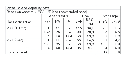
I attempted to measure my system flow with a short 3/4 inch ID hose from my well tank, through the intercooler and then the radiator. Approximating my car system, filling a 5 gallon bucket in about 15 seconds required about 3 psi (0.2 bar) at the IC inlet.
The required hose and pump size (52 GPM for 10 degree water rise) is space, power, and cost prohibitive. Consequentially, I used the largest pump and hose sizes I could reasonably afford, find, and fit. This wound up being a Johnson SPX CM90 pump that flowed according to the following chart, with some of the plumbing 1 inch hose and some 3/4 inch hose. The Johnson pump draws 7 amperes and is fairly quiet.
I believe the CM90 pump is a logical compromise, since pumps in commercial 650 HP engines with short hoses and high flow water systems are around 25% of the CM90 size. My system has fairly short hoses and uses a large radiator. I used the largest hoses I could fit in each run area.
While far less than ideal, the CM90 pump has proven to be adequately sized for intermittent short running. Data logs show the peak air intake temperature increasing approximately 45 degrees F over starting idle air during an eight second run. The largest problems in my system appears to be the lack of forced air across the Volkswagen radiator at idle and low speeds, and lack of enough water flow rate to keep the IC water cool. My car's radiator fan is tied to the engine cooling radiator's water outlet temperature, not the intercooler. This causes the VW radiator to idle around 20-30 F over ambient air temperature. UPDATE: I corrected this without an auxiliary heat exchanger fan by running my Derale fan controller at about 30%, with the engine radiator fan controller commanding more air only if the main radiator cold tank gets warmer than 145F.
On a 90 degree day in sunshine, starting intake air temperature and IC water temperature is about 112 F. This is prior to running the radiator fan at 30% speed minimum.
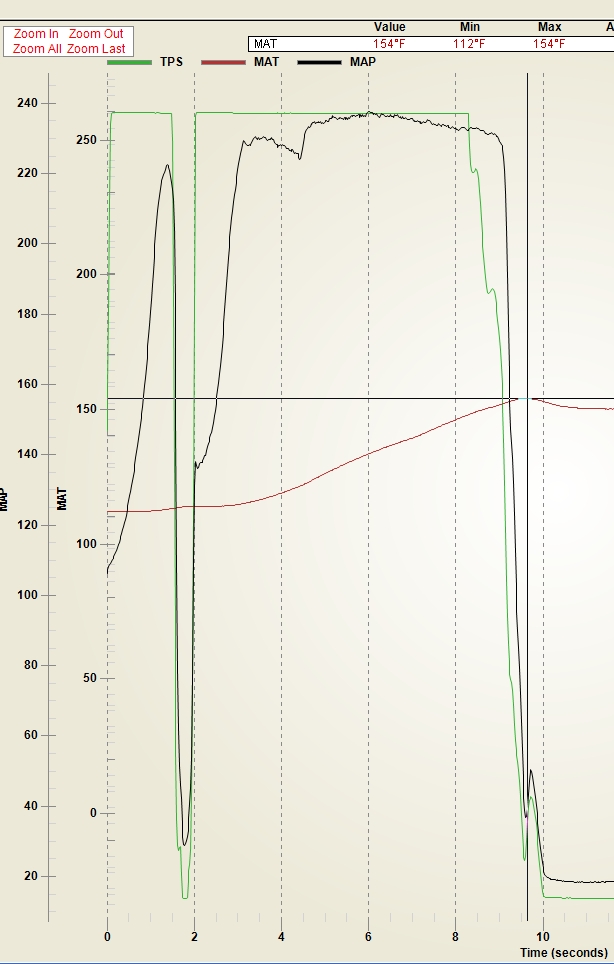
The log graph below is on drag radials, and shows time from brake release. This low nine second 1/4 mile run is on 275 drag radial tires. I had to lift throttle at maybe 1000 ft because the car got a little unstable at speeds over ~150 MPH. As boost built to 17.6 pounds, the car required one full throttle lift to bring the rear tires back into traction. You can see that lift where the throttle TPS line drops to zero just before 2 seconds. The logged data is throttle position, mass air temperature, and mass air pressure. Pressure is in kilo Pascal's, with 100 kPa MAP being 0 psi boost. The peak boost in the log is 240 kPa, which is 20.6 psi boost.
In the log graph below, starting air temperature is 112 F. During the run at wide open throttle, highest air temperature is 140F. The peak air temperature of 154F occurs after the throttle lift near the end of 1/4 mile run. That peak is with the throttle closed, the154F is probably just caused by engine heat pumping back into the intake manifold from the fully closed throttle. This is typical of the approximately 25F rise I have been logging during a 1/4 mile pass.
UPDATE With my fan controller modified to run 30% minimum, I now start every pass with the IC at ambient air temperature.
The above graph shows me I still have a starting air temperature issue. If MAT started at 90 F instead of 112 F, the ending IAT would be 22 degrees cooler, or about 120F. Still, my ending temperature with 21 psi boost is less than the typical temperatures logged with the supercharger and no intercooler. By calculations using 21 psi boost and 90 degrees F ambient air, with a 60% compressor efficiency: (21+14.7)/14.7 ^ .28 = 1.28 1.28 - 1 = .282 * (460+90) = 155 F 155 /.6 = 259 F I have pulled air temperature down from an estimated 260F on a 90 degree day to less than 150 degrees, even while the starting base temperature was 30 degrees hotter than ambient. The type 26 with a VW radiator and CM90 pump, without a constant cooling fan on the radiator in staging, has lowered air temperature entering the engine by somewhere around 100-120 degrees!!
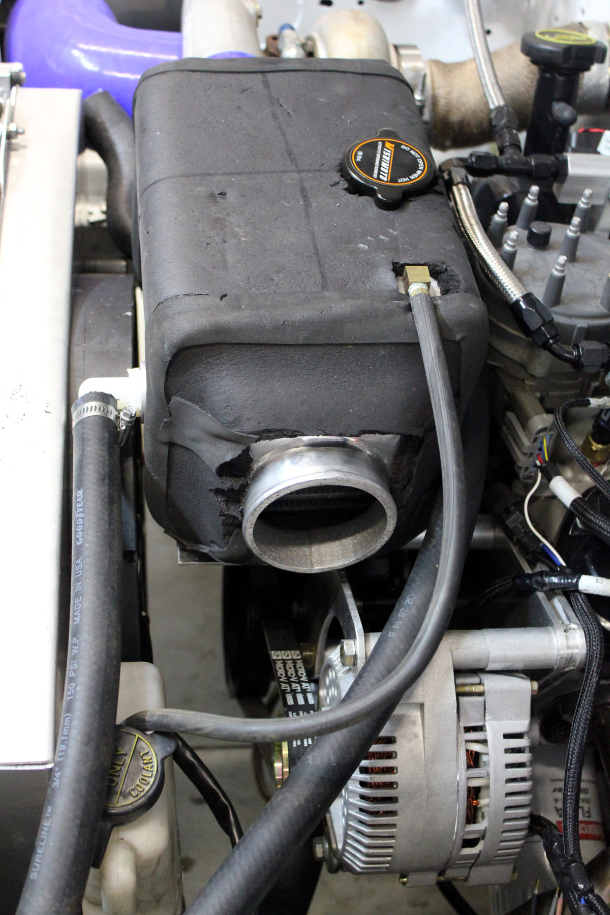
Mounting Position
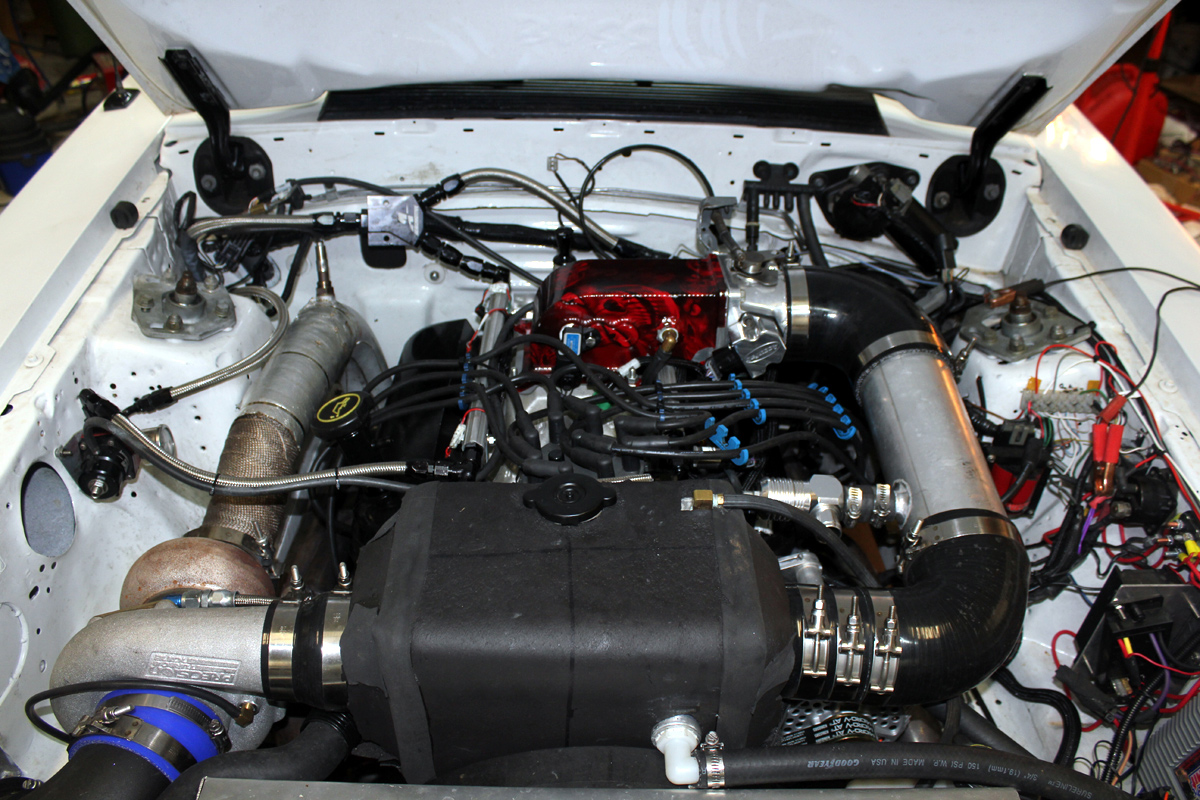
Trapped air is the enemy of water cooling systems. My Mustang's most convenient intercooler mounting position is above the water pump. For height reasons, this location prevented using a vertical water inlet and exit. With intercooler water ports out the front and rear sides of the type 26, the area above the ports formed a large air-trapping pocket. A second problem was installing a fill tank and reservoir. Because of low hood clearance, a standard water reservoir could not be located significantly higher than the intercooler. This further complicated trapped air problems.
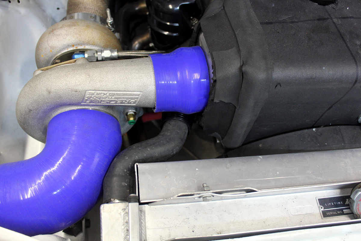
The boosted air path is excellent. The air system path is straight in through the turbo, directly out to the intercooler, and then through two 90 degree four inch diameter turns into the elbow. It is impossible to have a shorter path with fewer bends with the same size intercooler. My turbo easily makes over 22 psi boost, and makes that boost within 1.2 seconds from idle. This system makes 15 psi less than one second coming off idle. The highest dyno pull peaked 1280 HP at 28 psi, but until handling problems are worked out, I am keeping boost at 22 psi or less.
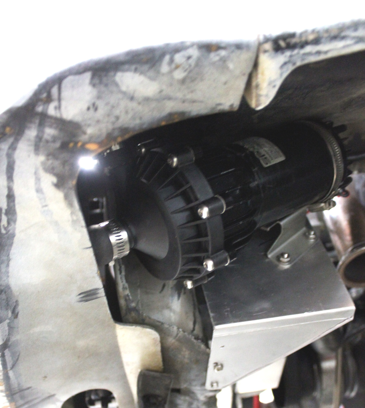
To save space, I added a Meziere WP311S electric water pump and an electric fan system for the engine.
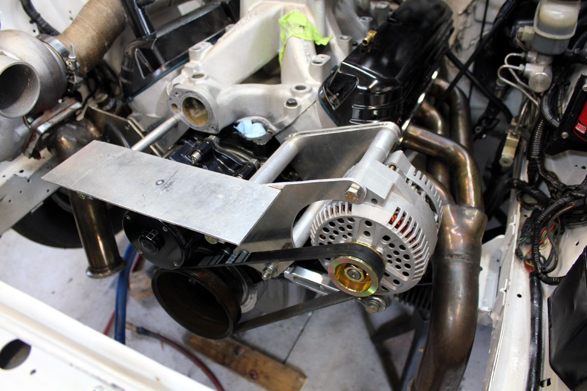
fig 1 above home made alternator brackets and intercooler shelf. If I can't find it, I make it
The advantage of this layout is I can fit either a centrifugal belt driven blower or a turbo. The air piping is straight and direct, as shown below:
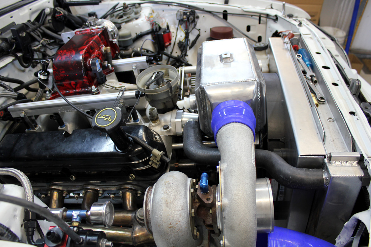
The outlet side goes through two 90's total, each are four inch:
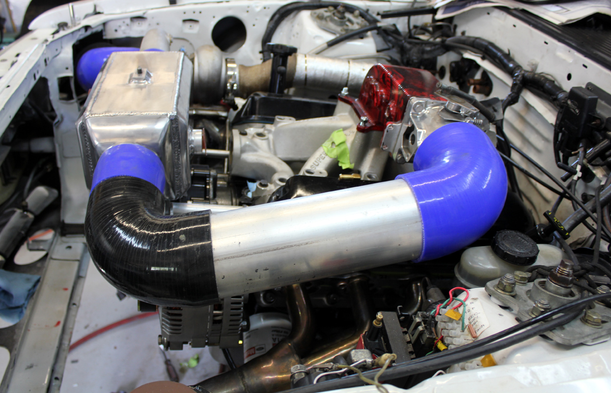
fig 2 The air-water-air system allows short, direct piping. The BOV welds into the four inch aluminum pipe. The BOV only has to bleed down the area from the throttle body to the turbo outlet.
Heat Exchanger
Nether the radiator nor the intercooler have published BTU or water flow rate specifications.
I chose the radiator empirically. There are three things working in my favor to reduce worries about radiator size :
After much searching and measuring, an early Volkswagen Jetta or Golf radiator looked workable (and cheap to replace if it didn't work):
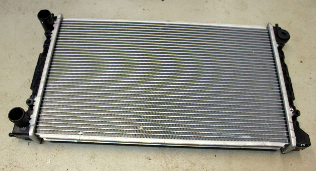
In addition to two large hose fittings on the same end, the VW Golf radiator has one tank vent. That vent is located at the tank top right next to the upper radiator inlet hose (left lower corner of pix). The nipple fits a small 3/8 inch hose for purging air. To ensure rapid full air purging, the small hose fitting must remain open to allow air escape while filling. Notice the radiator does not have a cap. It was designed for an external reservoir and fill cap.
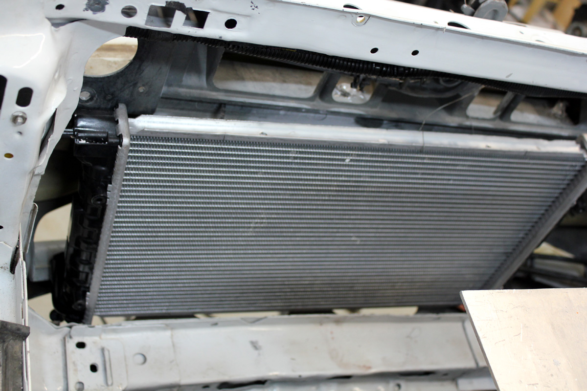
With a draw-through fan on my radiator system, the VW radiator fits perfectly between my automatic transmission cooler and the engine radiator. The top air purge vent is at the left. The hose outlets face forward. This is a dry fit while I made mounting brackets:
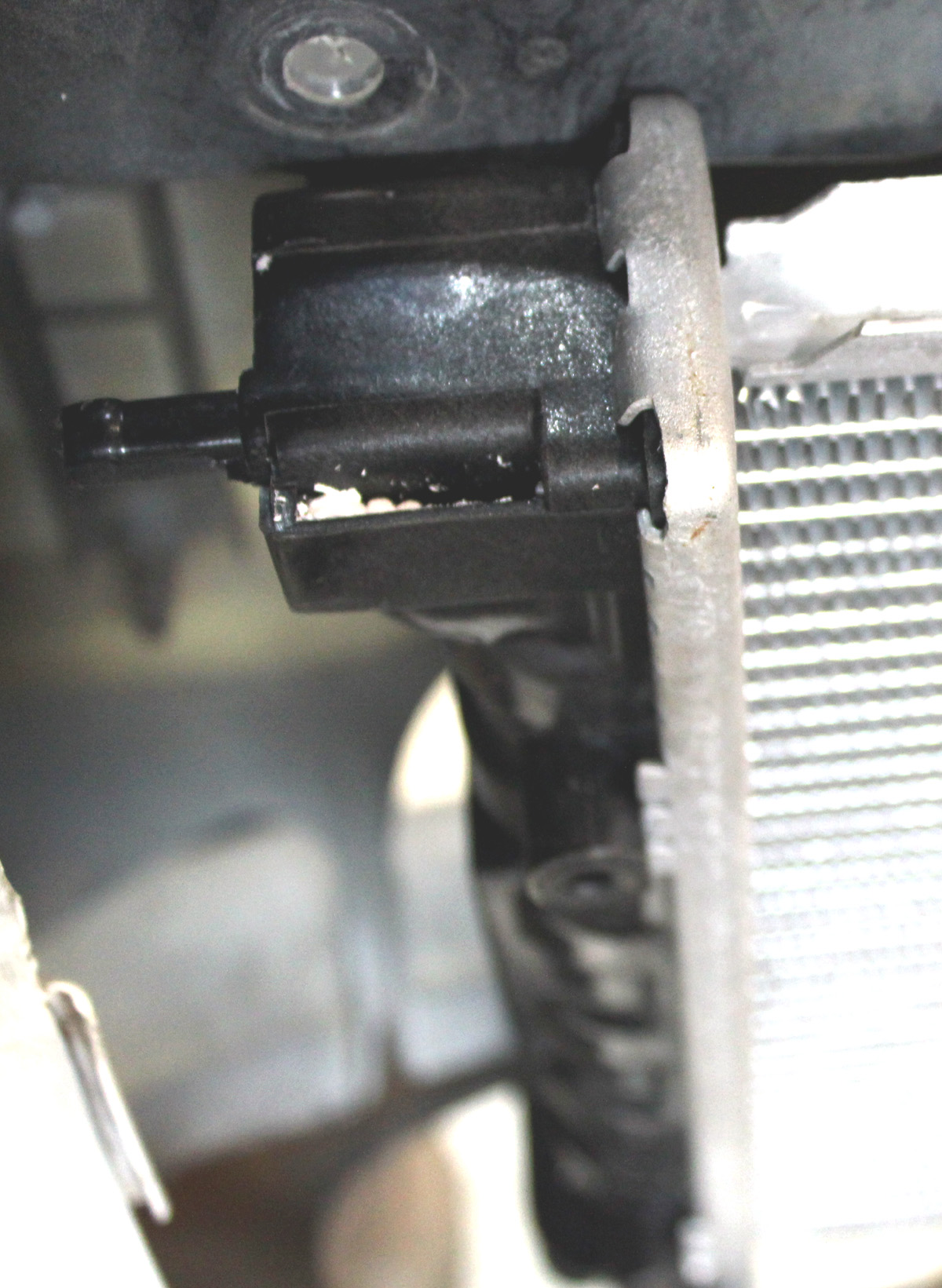
Close up of upper vent:
Water Circulation System
I thought about ice, but ruled it out because of headaches. I decided to use air-water-air. The circulation system looks like this:
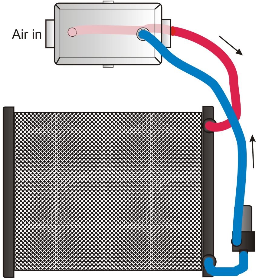
Head caused by lift is unimportant in a closed circulation system, as is acceleration head. This is because liquid flows with gravity as much as it flows against gravity. Since drop equals lift distance, the two effects completely cancel. Fluid velocity is also identical at the pump inlet source and the pump outlet. The pump does not have to accelerate fluid from a stopped position, fluid velocity toward the pump inlet equals fluid velocity exiting the pump, it is a closed loop.
Friction losses in hoses and restrictions are the only things causing head in a closed system. Unless you are dumping the water out to atmosphere at some greater height than the water source elevation, the system has no head other than frictional restrictions.
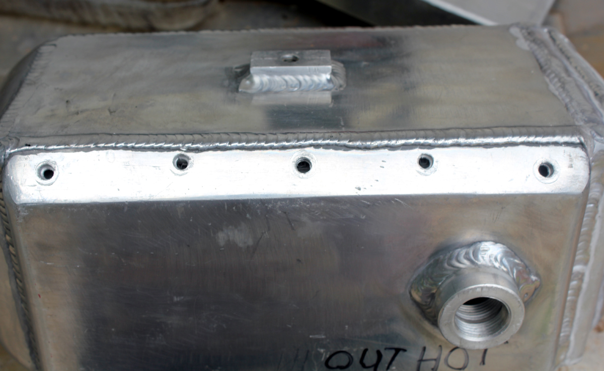
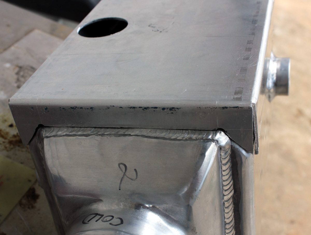
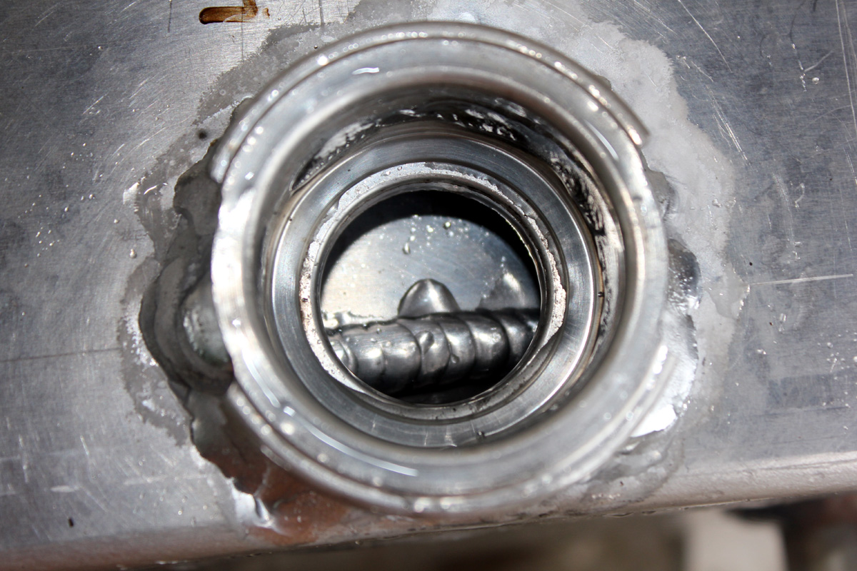
Type 26 Modifications
My vehicle's under hood height limitations, along with the high intercooler location above the engine's water pump, caused a system fill problem. I needed horizontal inlet and exit locations for water and air, and I did not want to trap air in the intercooler. This dictated a water reservoir above the intercooler height, and some way to purge air from the very top of the intercooler, well above the hose inlet and outlet. Without that, the intercooler would form an air trap and collect system air.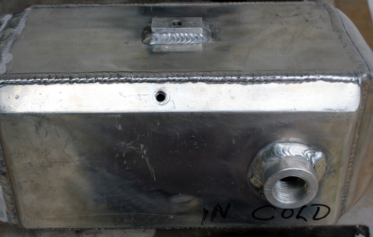
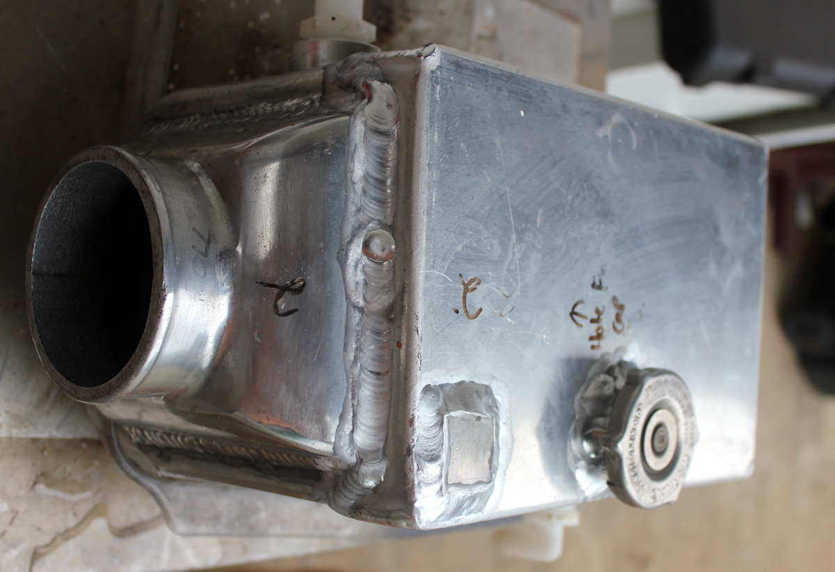
Intercooler water pump mounts on a home made bracket below the right front corner below the inner fender liner, but above the lower radiator support and bumper:
Final System
This system easily runs over 150 MPH in the 1/4 mile. Because of good plumbing layout, the turbo spools from fast idle to 15 psi in one second, and off fast idle to 20 psi in 1.1 seconds. Due to traction and handling, I'm limiting boost to 20 psi. I've had boost as a high as 28 psi.
kW, BTU, Joules, and Temperature
I wanted an idea of how much water flow is required, but I don't know much about thermodynamics. A list of relationships or conversions between units follows. I gathered this information from various textbooks:
For Water:
One BTU is the energy required to heat or cool one pound of water 1° F
Specific weight of water is 62lbs/ft^3
Water weights 8.35 pounds per gallon
62 BTU raises temperature of 1 cu ft of water 1 degree
For BTU, joules, or watts:
One kilowatt-hour is about 3412 BTU
One joule or watt-second is 0.000948 BTU
One BTU is approximately 1055 joules or watt-seconds
For air:
0.018 BTUs per cubic foot changes temperature 1° F
1 BTU changes 55 cu ft. of dry air 1° F
0.24BTU raises one lb. of air by ~1deg F
One cubic foot of dry sea level air weighs .07 lbs.
For Engine Airflow:
One HP uses approximately 2 CFM of air
Specific heat of water is 4.1813 times specific heat capacity of air (this means a pound of water absorbs about four times the heat of a pound of air, water is one of the best heat absorbers in nature)
Water flow was calculated above based on steady operation and 10F rise, with 262,000 BTU per hour. Drag racing takes around 5 seconds in the 1/8th mile, and 8 seconds in the quarter mile. A ten second full load time would be conservative. There are 360 ten second periods in an hour. This means the total heat dissipation would be 262,000/360 = 728 BTU.
Water temperature increases 1 degree F per pound per BTU. My system holds approximately 2 gallons of water, or 16.7 pounds. 728 BTU would increase temperature of 16.7 pounds by 43.6 degrees. Without any cooling from the VW radiator, if water circulated all 2 gallons in ten seconds (a 12 GPM rate) the water would reach 44 degrees over ambient at the end of the pass. 4.4 times that rate is 52.8 GPM, which tracks with the 10 degree rise calculation of 52.36 GPM. Using this entirely different way of estimating GPM, we find close agreement with earlier formulas. This assures us the numbers are correct.
My worse case water rise should be somewhere around 20 degrees F. I wound up with about 30 degrees air temperature rise over a 1/4 mile pass at 21 psi boost, so I expect the water rise is pretty close to estimates. Water temperature rise has to be some amount less than air temperature rise. The type 26 seems to work adequately at over 1000 HP.