Two things always bothered me about my E F Johnson Viking Valiant and E.F. Johnson Ranger transmitters:
- When I would put the VFO on spot and listen to the beat note on higher bands, the beat frequency changed significantly as I activated and tuned the power amplifier.
- Sometimes I would get incurable chirp and frequency jumping on higher bands, generally worse when the VFO was running straight through on 40 meters (later stages not multiplying).
Finding the problem was a fairly difficult job. I tried resistor loading the VFO output to further buffer the VFO, I tried adding voltage regulation to the plate supply of the VFO tube, I even added an additional buffer circuit, and added extra RF bypassing. I tried cleaning the panel bushings on the VFO. I finally figured out the problem was ground currents looping through the shafts and front panel, and getting into the VFO through the VFO shaft and other housing shield gaps. See how a shield works at this link.
Problem Cause
E.F. Johnson, in many rigs including the Ranger 1, Ranger II, and Valiant I and Valiant II, isolated the plate tuning capacitor from the chassis. E.F. Johnson used insulated washers to isolate the frame and shaft, and grounded the capacitor only through a long thin lead to a single point connection at the PA tube socket.
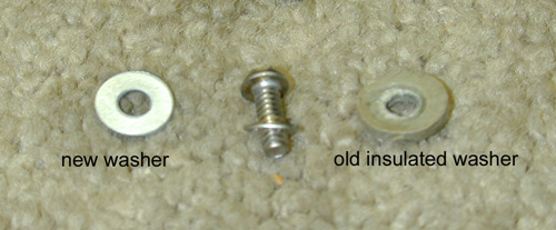
Typical insulated hardware.
Tuning capacitor fames (rotors) mount on insulated washers.
Replace them with stainless steel.
This capacitor mounting arrangement is a source of frequency instability and chirp, and even causes the VFO to run on a slightly different frequency when the rig is transmitting then when the rig is on "spot". The capacitor mounting also causes TVI!
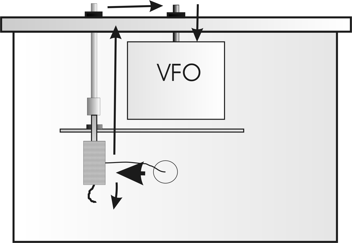
Harmonic and fundamental current path caused by:
1.) insulating plate tuning capacitor from the chassis
2.) insulating the capacitor front bushing from the shield
3.) imperfect grounds on front panel
The imperfect ground on shaft entrance of VFO shield allows a portion of the plate tuning capacitor currents to enter the VFO housing.
This causes the VFO to change frequency in proportion to plate tuning capacitor currents. It also allows harmonics from the PA tube(s) to pass through the front panel and cabinet shielding, where they can radiate and cause TVI.
I think I
understand the basic
thought-process
Johnson engineers
had. They just
didn't consider the
impedance of the
ground paths and the
problems they were
adding. In effect,
they unintentionally
added a path that
partially bypasses
the low-pass tank
circuit for
harmonics and
also increased the path
length for
parasitics. The
negatives of doing
this far outweigh
any unlikely
improvement created
by using a
common single point ground.
My guess is one or
more of the original
engineers grew up
with wooden chassis
breadboard radios
and transmitters.
Old wooden chassis
radios used a single-point RF
ground. This was
because there was no
large highly
conducting
groundplane (the
metal chassis)
available.
The single point RF
ground
practice was very
common, and was
often a requirement
in wooden chassis
equipment! Without a
single ground point
for each stage, old
radios could be very
unstable.
Unfortunately this
practice does not
transition into
metal chassis
equipment,
especially when
shields and extreme
amounts of gain are
involved.
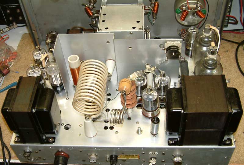
The chirp and instability (and TVI) problem is rooted in the high circulating current of the tank, and the fact the tank is grounded to the chassis only by a single thin wire connection at one end of the capacitor frame.
Viking Valiant chirp and TVI mod
The plate tuning capacitor shaft routes through but is insulated from a metal shield. Shafts should always be grounded to shield walls, otherwise they are a source of conduction through the shield.
Not grounding a shaft to a shield renders any shield partially or totally ineffective.
This is also true for ingress, any shaft going into a shield, like the VFO box, should be grounded to an effective RF zero point. Unfortunately the front panel is not an RF zero point, because the shield wall is not an enclosure, and the partially RF floated capacitor shaft couples RF to the front panel.
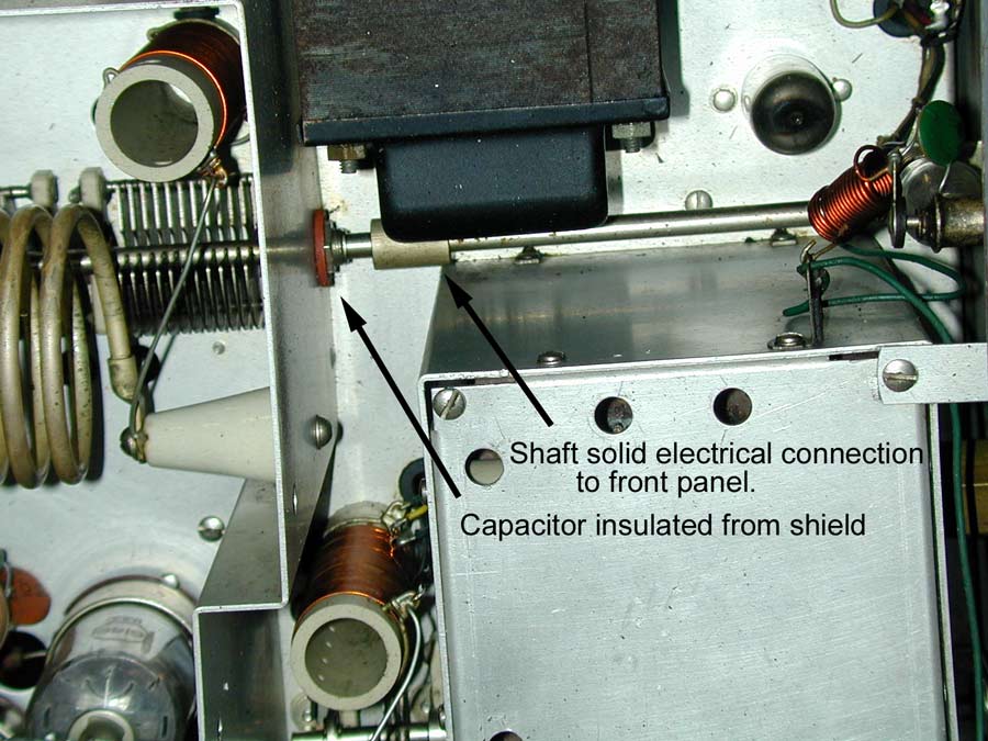
Note the capacitor shaft bushing is insulated from the shield, and the shaft coupler is NOT insulated.
This is a huge mistake because if the frame of the capacitor has any RF potential to the chassis the shaft will carry RF current to the front panel. This means the capacitor shaft will radiate unwanted RF, including harmonics, outside the shield walls.
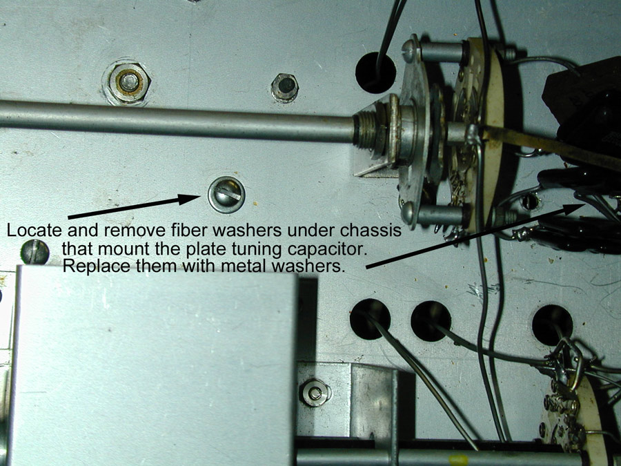
The frequency jumping, frequency instability, frequency movement when adjusting tuning or loading, and chirp can most easily be cured by removing the fiber insulating washers under the chassis and replacing them with thickly plated or stainless steel washers. Use a little dab of dielectric grease under the washer to prevent corrosion, or place a star washer under the flat washer to "bite" into the chassis. Stainless hardware will not corrode as readily as galvanized steel, and will generally retain an electrical connection much longer.
I could have replaced the plate tuning capacitor shaft coupling with an insulated coupling, grounded the tuning capacitor shaft, or corrected the problem in any number of ways. I decided this was the least invasive way of solving the problem.
Johnson Ranger and Ranger II
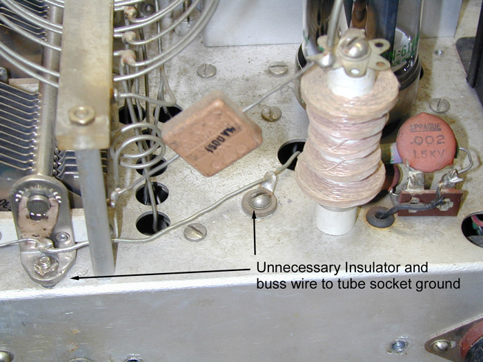
There is no reason at all to run a 5 inch ground buss on the plate tuning capacitor.
Remove the insulators and the buss wire going to the tube socket.
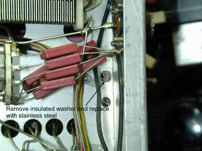
Remove both under chassis washers on the tuning capacitor, and one by the rear of the bandswitch that has loading padder capacitors.
Use steel washers to ground them directly to the chassis.
If you pass this information along or steal it for your own web use, please give me credit for the initial work. It took me several hours to find this problem!
copyright 2004 W8JI