Lifting Rohn 45G 25G tower
|
Lifting Rohn 45G 25G tower |
|
Installing new 200-foot Rohn 45G TowerRotating Tower page Contesting and Boatanchor Room Antenna System and my house station In an effort to upgrade towers I needed to replace a 195-foot Rohn 25G with a Rohn 45G tower. Rather than totally disassemble the 25G tower section-by-section and install the 45G section-by-section, we used the following method......
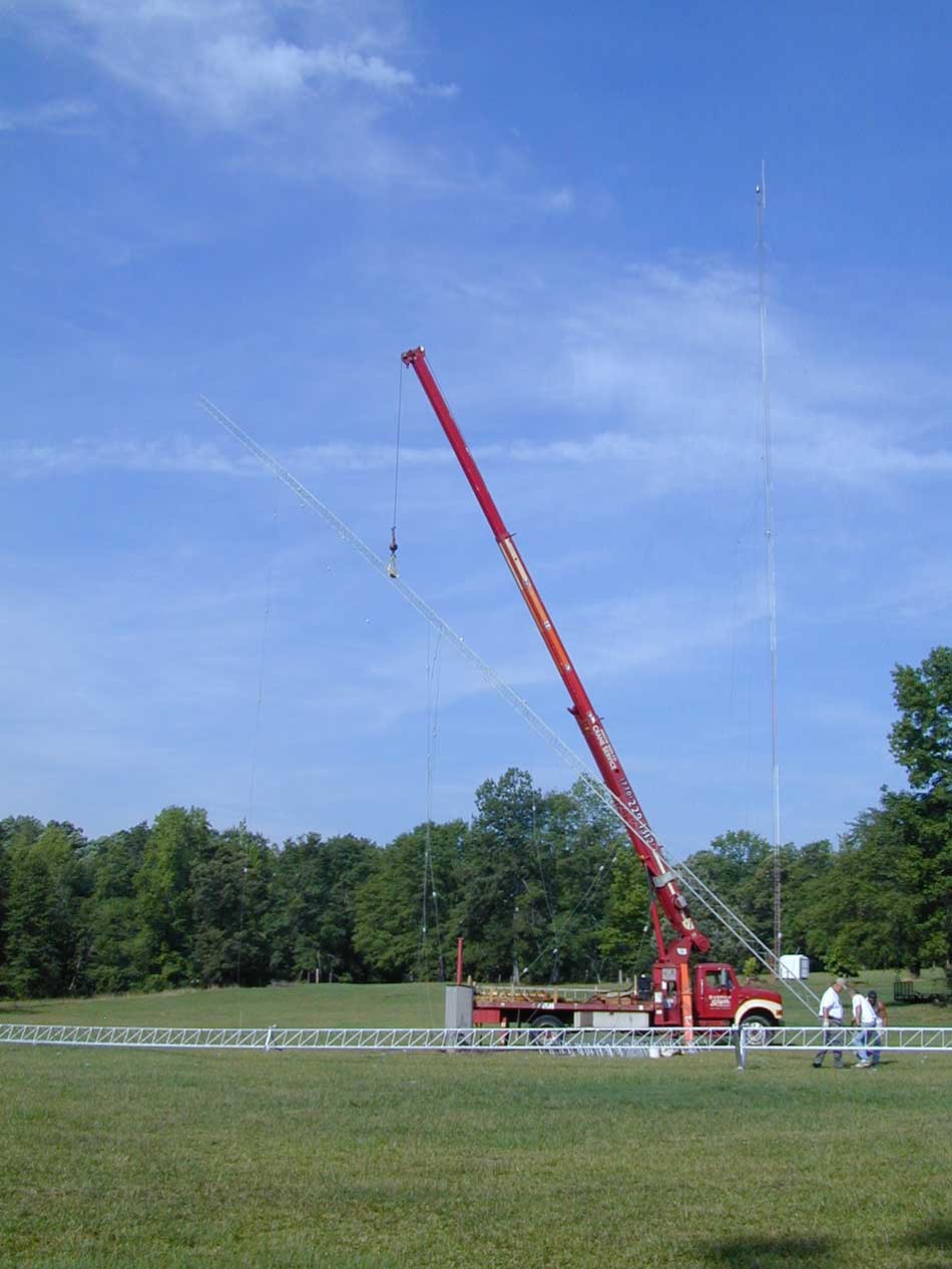
The 25G coming down from 195 feet to 110 feet for the crane lift.
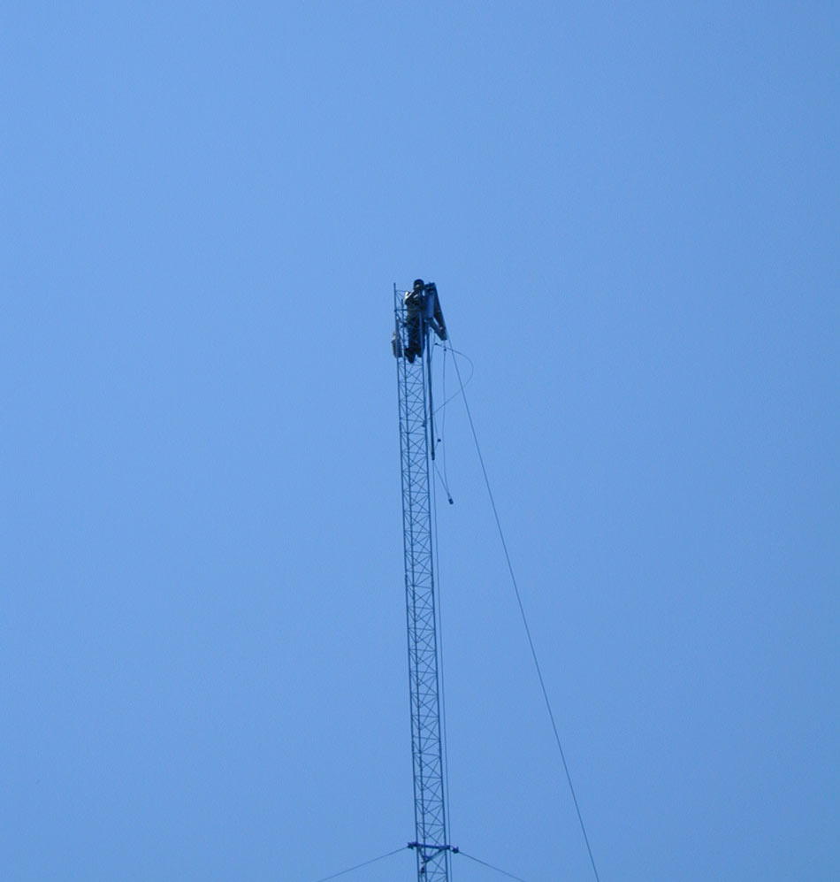
Removing erection fixture prior to attaching the sling to the Rohn 25G.
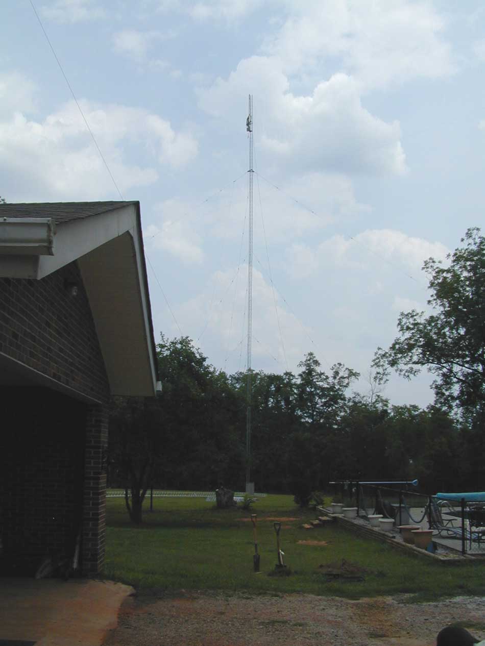
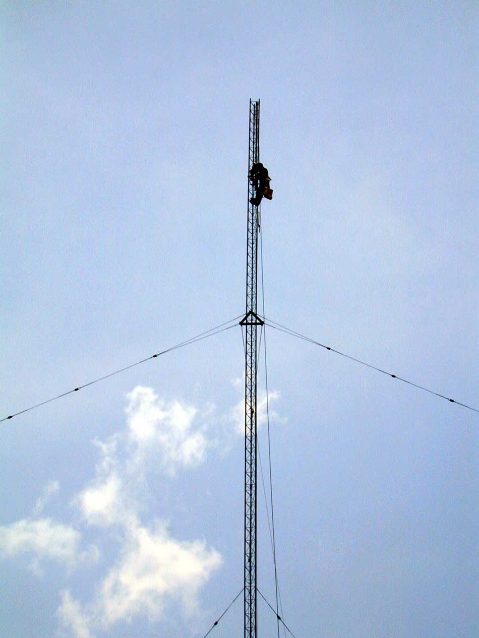
This Rohn 25G floats on an single insulator, and was 195 feet high. It supported my 160 meter four square and served as an omni directional antenna. The Rohn 25G was stripped section-by-section to 110 feet. In this picture Justin Storey climbs down after attaching the cloth crane sling to the tower at the 75 foot level. A new Rohn 45G is waiting to be lifted.
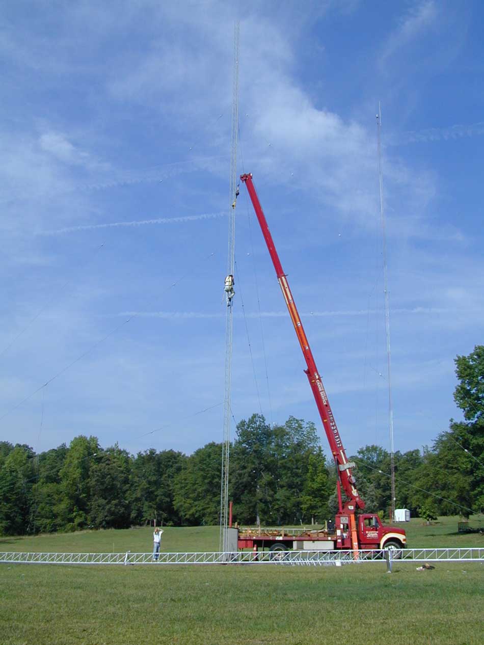
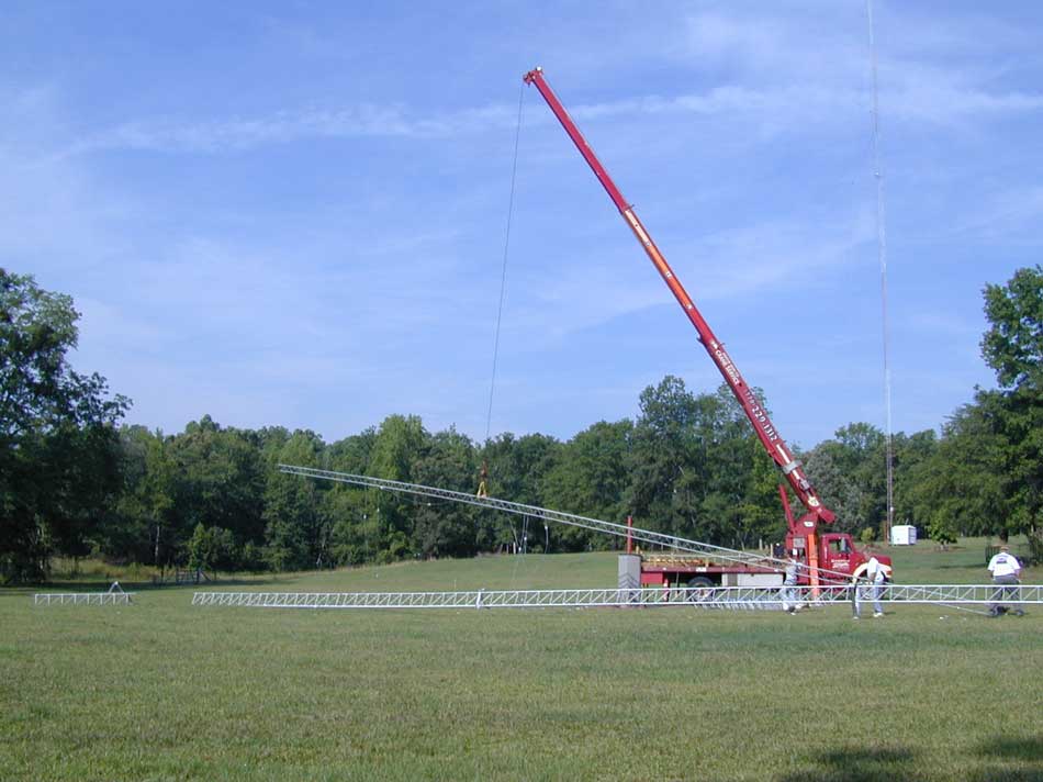
WW4LL Fred acts as a spotter directing the lowering effort as W8JI Tom and Justin walk the tower base out away from the insulator as the Rohn 25G tower is lowered.
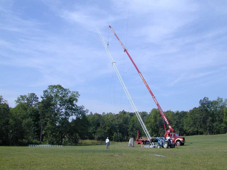
The Rohn 25G is at 45 degrees. There is hardly any bend or flex in the tower, it comes down smoothly in one 110 foot piece.
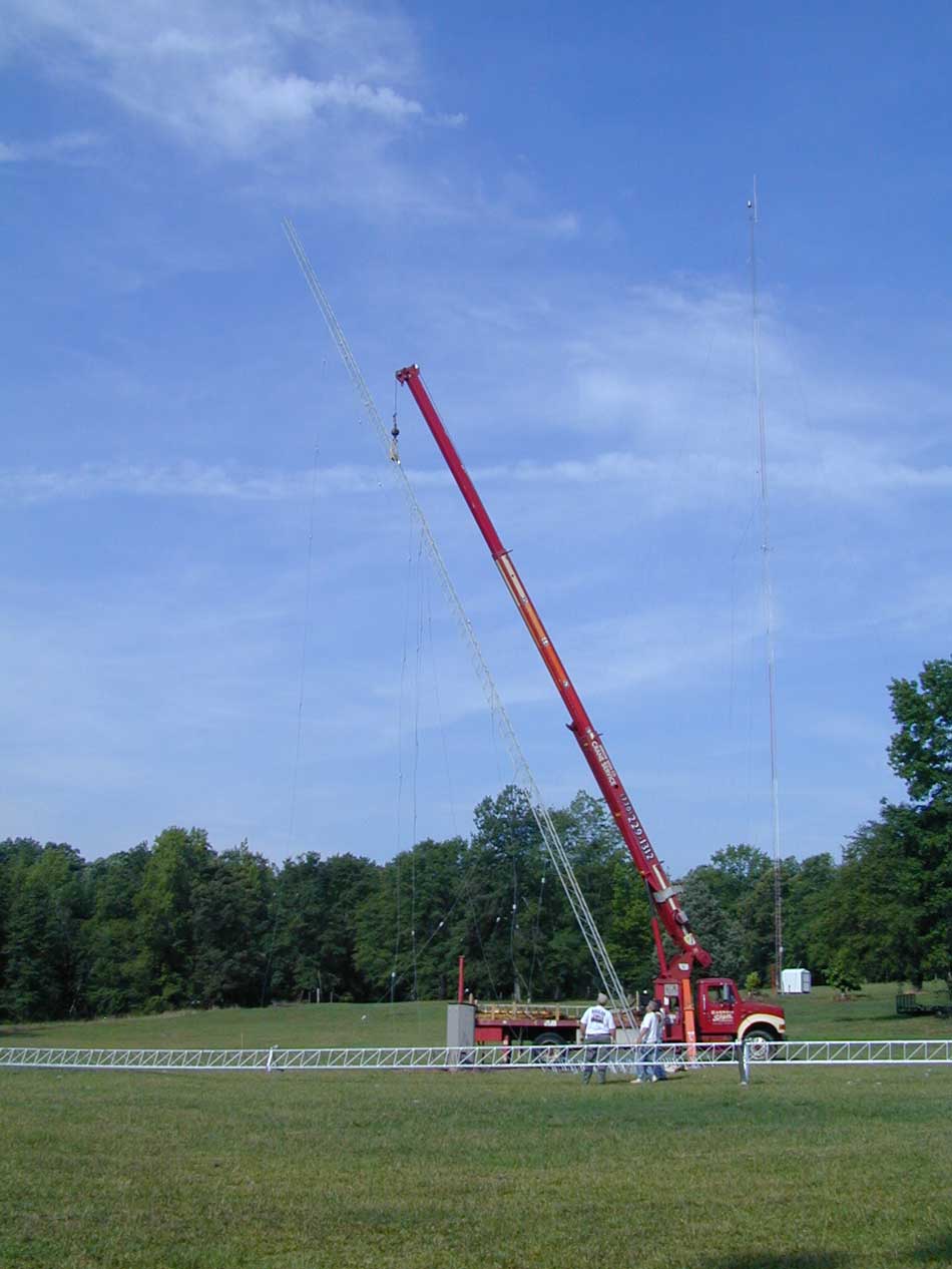
This is the worse-case bending point for the 25G, since it is almost horizontal. Notice there is almost no sag in the tower. Despite being over 20 years old the 25G didn't bow or bend with a single lift point at 66% of tower height. Never lift at a section joint, lift in the middle of a section and attach a soft sling around the whole tower while wrapping around one leg to avoid sling slippage.
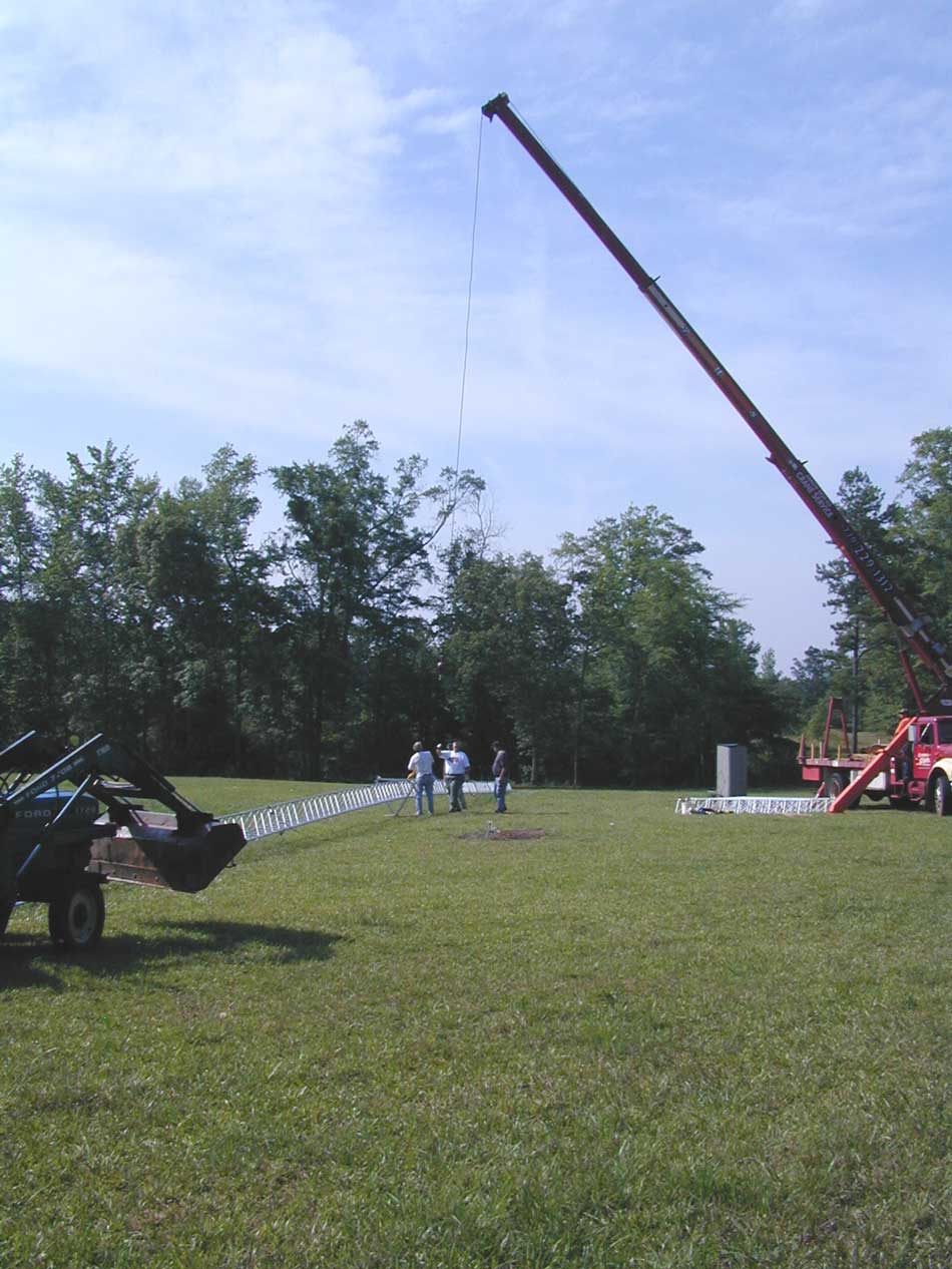
The new 140 foot tall 45G ready to lift. Because the fully extended crane jib was too close to load limit, we removed two sections. This made the actual lift length120 feet. Guylines are attached to the tower while on the ground.
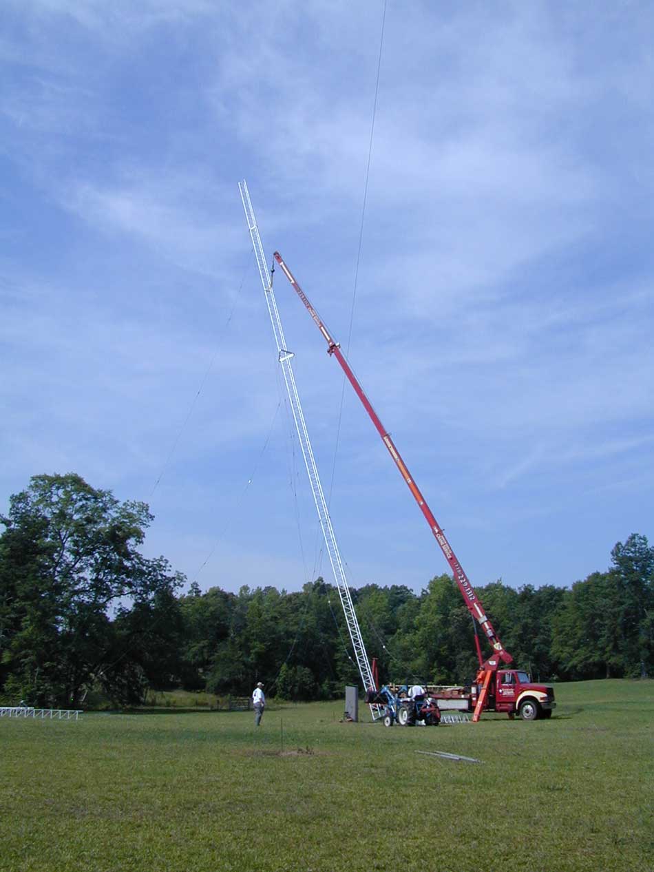
As the 45G goes up, the tractor moves the base towards the insulator. The tower went up smoothly.
Notice the base is held off the ground. Guylines at 35, 70, and 105 feet are dangling from the tower. You can see the 20 feet of 45 we removed laying to the left. This would have lifted fine, but the boom extension required would have put the jib too close to the limit. Instead we picked the tower at the 75 foot level. Again this was at about 2/3 of the full height in the middle of a section.
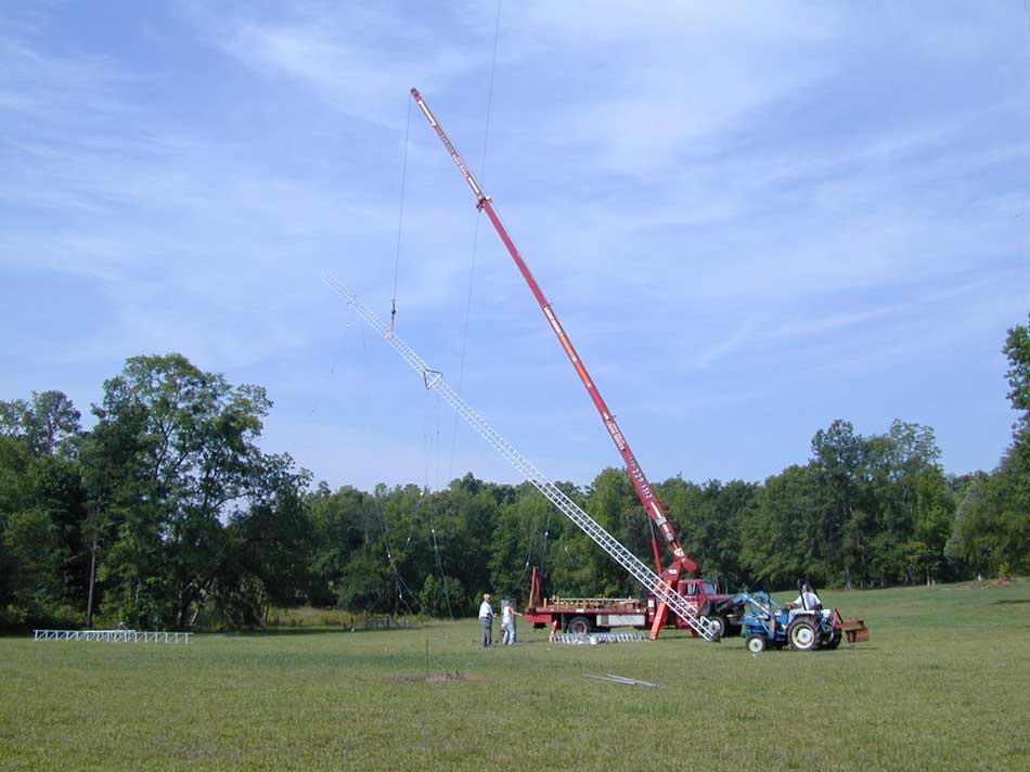
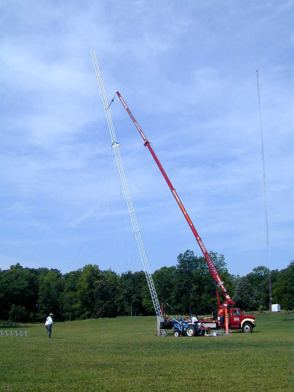
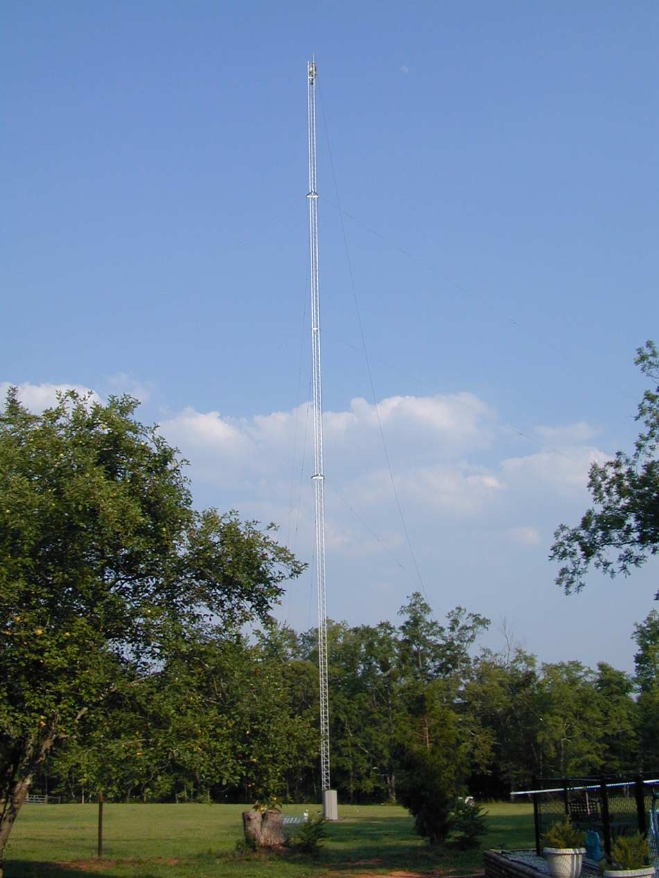
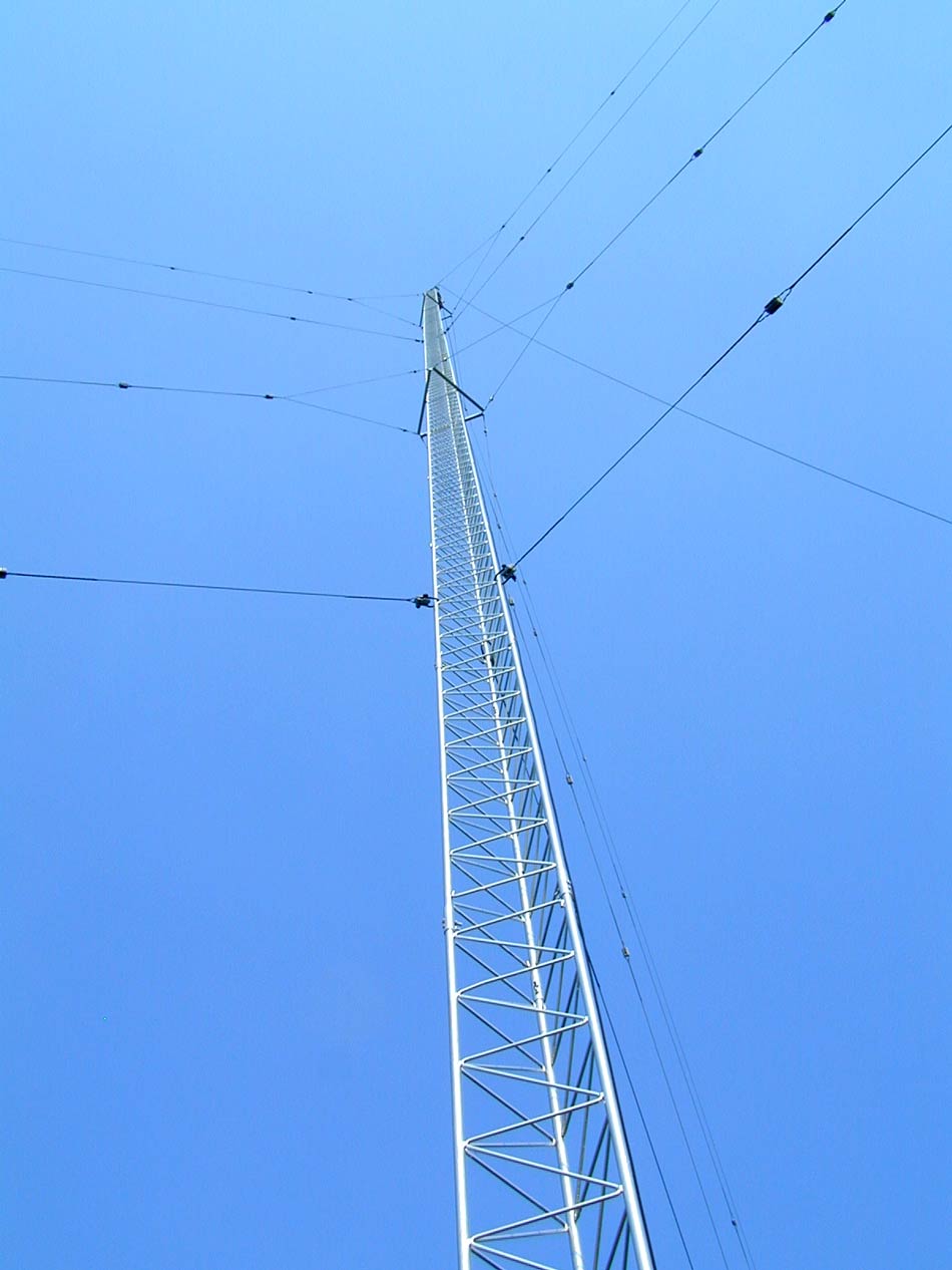
The tower is now nearly vertical and the base is getting close to the insulator. The insulator is a single pin point that floats. If all three legs are attached solidly to three insulators, it creates huge stresses on the insulators. For this reason I always use a single floating pin insulator. To restore torsional stability, guys at 70 and 140 feet are star bracket guyed. This will allow stacking of 20 through 10 meter Europe yagis on the tower. The tower will become the run tower for 20-10 meters while still working as an insulated base series-fed tower on 160 meters.
This new 200-foot tower will also support 160 meter four square elements (each 1/4 wave long) and long ropes that attach to ends of 80 and 160 meter dipoles on the 300-foot tower in the background and a rotating tower. Antennas are in the clear and well away from other antennas. The 300-foot tower is 500 feet away. This system is carefully planned to avoid interaction or having antennas beaming through obstructions.
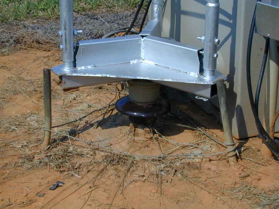
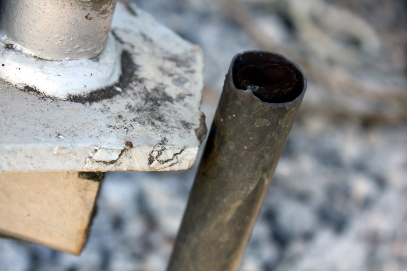
The copper pipe forms spark-gaps for lightning protection. The base is home-made from a standard Rohn pier plate. The rectangular steel tubing is welded to a vertical 1-inch diameter solid steel rod that is machined to fit the insulator pin. The rod floats on the insulator top pin to prevent insulator twisting or rocking stress. Radials and copper ring are brazed to copper pipes. After installation, radials and ring were covered with landscaping cloth and driveway stone. Copper pipes are bent in or out to set spark gap distance.
The 140-foot level star guying bracket is lifted into place. The 105-foot guy bracket is visible at the photo bottom.
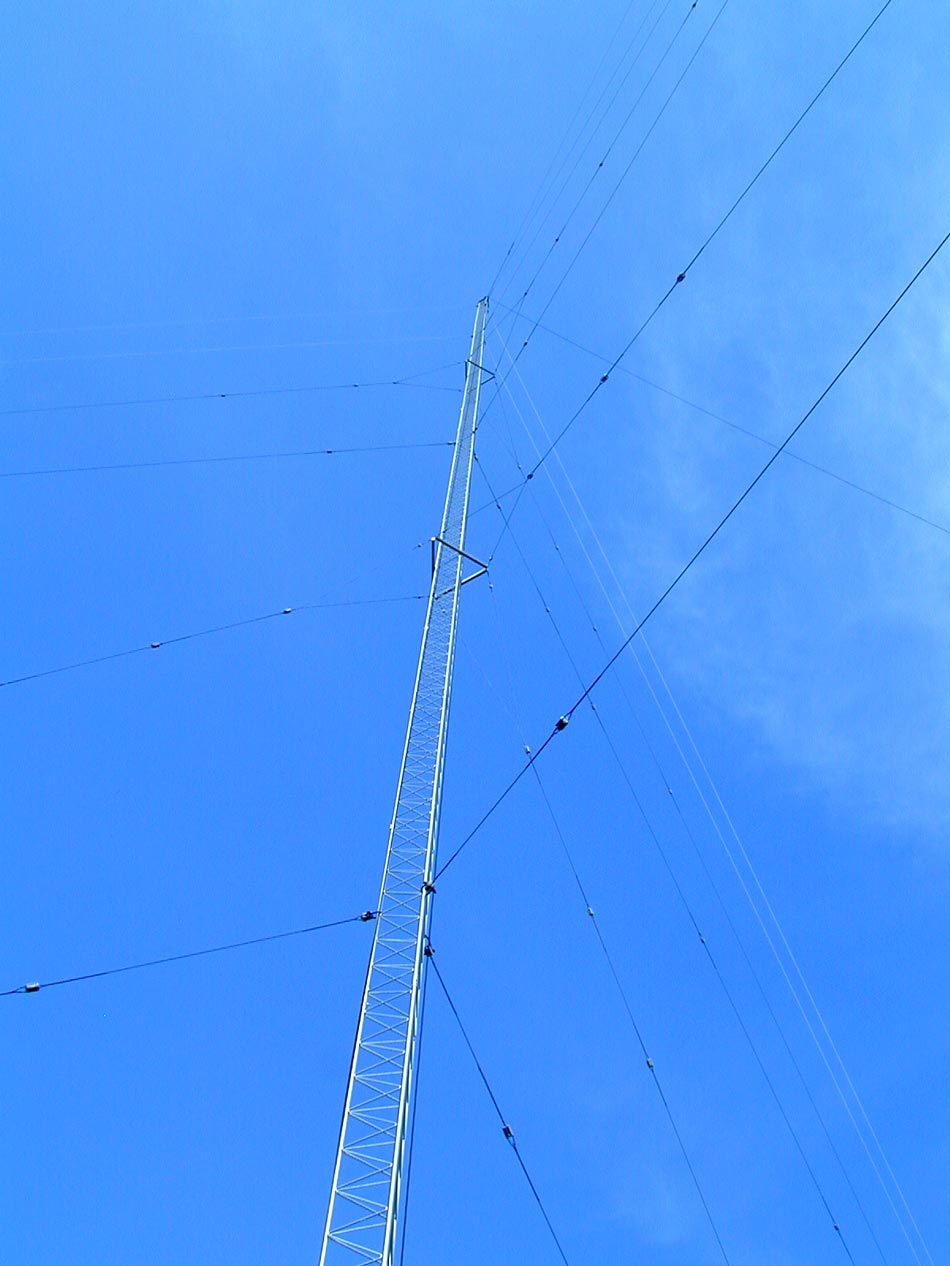
The 45G at 170 feet. Waiting the final sections and upper two sets of guy lines.
The erection fixture is moved up into position to lift more tower. The 175- foot guy bracket is visible near the top.
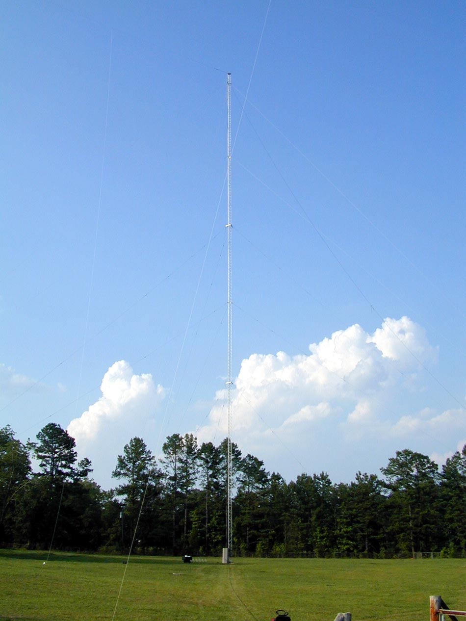
The new tower, still incomplete and not at full height, but after a good day's work.
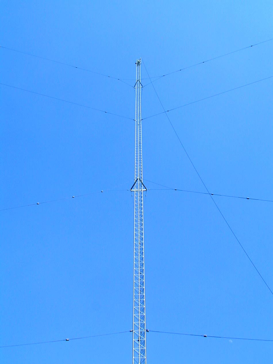
Below...the full tower completed after two weekends. Top two layers of guys are 3/8 inch fiberglass rod. Bottom layers all 1/4 inch EHS.
Two of the legs are aligned so the Yagis can be bolted directly to the flat face using crossover plates. This simplifies aiming fixed beam antennas at Europe. Part of an ongoing upgrade with the New Contest Room
|