Related Pages:
Groundplane Verticals (they are generally end-fed 1/4 wave radiators)
Technically a true "longwire" needs to be at least one wavelength long, but Hams commonly call any end-fed wire a longwire or random wire antenna.
Long wire or random wire antennas are very simple antennas. They can come close to half wave antennas in efficiency, although efficiency decreases as they are made very long or installed closer to earth. Like every antenna that exists, random or long wires have advantages and disadvantages.
| Advantages | Disadvantages |
| no heavy expensive coaxial feed line hanging from the span | single wire "feeder" and "ground lead" radiate |
| very simple to install and construct | can be a problem for lightning |
| excellent stealth antennas | single wire feed line can be burn or shock hazard |
| inexpensive | require a tuner or matching system |
Because the radiating area is often brought into or near the operating
position, longwires often create RF
interference to consumer goods or RF
in the operating
room. The easy
installation part
comes from generally
needing only two
supports, and not
having a heavy
feed line hanging
from mid-span like a
dipole. The
long expensive feed cable
normally associated
with a doublet or
dipole is not
needed, the antenna
wire itself serving
as a "feed line".
The end fed 1/2 wave antenna, much like the 43 foot vertical, has become a cult phenomena.
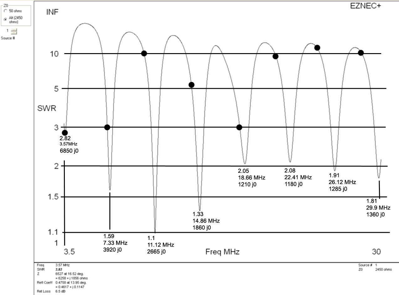
This is the feed impedance and SWR of an end fed 80 meter half wave with an ideal 49:1 transformer and good stable counterpoise or ground. The black dots represent exact harmonics of the 3.57 MHz fundamental resonance. The actual resonance, 49:1 transformed SWR at resonance, and the antenna impedance at resonance are shown:
In a low loss system with good counterpoise, with a very good 49:1 feed transformer, in-band EFHW SWR is:
| Freq 3.57MHz | 7.33 MHz | 11.12 MHz | 14.86 MHz | 18.66 MHz | 22.41 MHz | 26.12 MHz | 29.9 MHz |
| SWR 2.82:1 | 1.59:1 | 1.10:1 | 1.33:1 | 2.05:1 | 2.08:1 | 1.91:1 | 1.81:1 |
| Imp 6850 j0 | 3920 j0 | 2665 j0 | 1860 j0 | 1210 j0 | 1180 j0 | 1285 j0 | 1360 j0 |
| In-band SWR 2.82:1 | 3:1 | 10:1 | 5.1:1 | 3:1 | 9.8:1 | 10.2:1 | 10:1 |
The antenna itself works just as well as any other wire of similar height and length. Any or all problems are in the counterpoise and feed system. The difficult problems associated with random wire or long wire antennas are caused by ground currents and radiation from the single wire feeder.
End-fed antennas, or antennas with the single wire feeder brought into the shack, come with a little misconception. One commonly repeated myth or "theory" is that half-wave antennas, being resonant, do not require a counterpoise, or that some magical length of antenna will prevent RF in the shack. This does not mean the antenna will be worthless and not make contacts, it simply means something else replaces the missing counterpoise area and we also bring RF fields right into the shack. The feed line, as well as everything connected to and surrounding the single-wire feed line and counterpoise, becomes part of the radiating system. This creates three potential problems:
1.) The feed line, mast, and things around the feed line connect through the antenna into the receiver. This brings noise into the receiver.
2.) The feed line, mast, and things around the feed line become part of the radiator. This brings voltage (electric fields) and current (magnetic fields) directly into the shack.
3.) The feed line and grounding affects SWR and tuning.
Since we often do not have a baseline for noise, unnecessary additional noise will often go unnoticed. The remaining two issues are more likely to be noticed, but only if we run enough power to cause RF burns, power supply shutdown, or other forms of RFI.
Transmitter power levels, feed line length and routing, and the susceptibility of equipment to RF problems greatly influence things we most likely notice. This is why some people (usually with QRP power levels) swear by end-fed half-waves, while others (usually with higher power) avoid end-fed antennas. The reason for that is simple, end-fed half waves have common mode feed line current problems affecting their performance, and these common mode currents cause inconsistency in user satisfaction.
In nearly all cases, if we notice it or not, an inadequate counterpoise hurts antenna pattern and efficiency. This is why high power stations often have more efficient, more ideal, antenna systems. Higher power very often excludes use of power wasting systems, because the wasted power often creates significant local problems. If 5% of 10 watts is exciting the desk with RF, it isn't any big deal. If 5% of 1500 watts excites the desk with RF, the result can be hazardous.
I wouldn't have a problem with a 1500 watt transmitter into a longwire antenna with a tuner remote from the shack and house. I would likely have a fire, or damage equipment, if I brought a single-wire feeder into the house! With 5 or 10 watts, I wouldn't care.
How the Longwire or Random Wire Antenna Works
The antenna element works the same as any other antenna. Electromagnetic radiation comes from current flowing over a spatial distance along the wire.
The single wire feeder not only radiates electromagnetic energy, it has very strong electric and magnetic induction or energy storage fields surrounding the wire for some distance out from the wire.
In order to force current up into the feed wire and antenna, the matching or feed system has to "push against" something else. For every milliampere of current flowing into the feed wire of the longwire antenna, an exactly equal current has to flow into a ground system of some type! In any non-terminated antenna, currents and voltages are transformed along the antenna. This transformation is caused by standing waves. This means ground lead currents can increase or decrease along the ground wire and everything connected to the ground wire or ground system. Voltage changes also along the ground or counterpoise system, just as it does in antennas. The voltage caused by antenna return currents, and the return current, will become stronger (more intense) or weaker (less intense) because of standing waves on wiring and equipment cases.
These ground currents, displacement currents, or common mode currents cause everything connected to the matching system to become "hot" with RF. The result is generally all sorts of RF interference to active devices or even physical harm to the operator, such as actual burns or on lower bands like 160-meters..... electrical shocks! These unwanted but very necessary currents ideally should flow through the lowest impedance path and widest area path we can manage.
Noise from Longwire Antennas
Radiation and fields surrounding the single wire feed system not only leak out, unwanted noise and signals can also leak in. Radiation from the feeder and everything connected to the matching system, as well as common mode currents, also allows common mode noise ingress. This deteriorates receiving system noise performance.
Common mode currents and induction field coupling also decreases transmitting efficiency. This effect adds unnecessary loss to the system.
If things are just right (like having a fairly good RF ground in the shack) and power is fairly low, we can often "get away" with having a random wire or longwire brought directly into the shack, but that is more a matter of good fortune than good planning.
Repeating and expanding on what was said above, radiation and fields surrounding the single wire feed system not only leak out, unwanted noise and signals can also leak in. This is an unsolvable problem with a single wire feed. The very best we can do is relocate these problems to an area where they cause no noticeable problems. We can do this by relocating the feedpoint. Relocating the feedpoint can move strong magnetic and electric fields away from the operating position, house wring, consumer devices, and our sensitive equipment. This reduces noise into the antenna feed system, and RFI caused by the antenna feed system.
Method 1, grounding
Ground rods have limited effectiveness, except perhaps on very low frequencies. This is not saying we should not have ground rods, but rather depending on them for RF grounds is not a good idea. The RF ground should if possible contain radials or counterpoise wires and not just ground rods. Ground rods do very little good for RF! As a matter of fact adding ground rods can decrease RF efficiency when an insulated counterpoise is used.
With fairly low power and good luck, one way to mitigate noticeable problems is a ground plane at room level. This ground system can be as simple as strips of foil laid under a carpet. These conductive wide strips of foil would then be connected back to a wide station equipment ground buss. Stained-glass hobby suppliers sell adhesive backed copper foil that works very well, and is easily soldered. Another choice is aluminum foil, but this requires pressure connections that tend to be less reliable over time. As an alternative to copper foil strips, a metal screen or grid of wires at floor level can be used. This system can be right under the carpet, or can even be directly below the floor. it is important whatever is used, that is have a low impedance RF connection to the cabinets or chassis all desk equipment.
This type of counterpoise system makes the entire room, including the operator, "rise" in voltage and match the equipment chassis voltages. It also disperses or spreads the current and voltage around, reducing intensity of localized electric and magnetic fields. This is very effective for a second floor (or higher story) RF ground. Like standing on a metal plate carrying high currents, there is little potential difference between different areas of the high-conductivity counterpoise sheet.
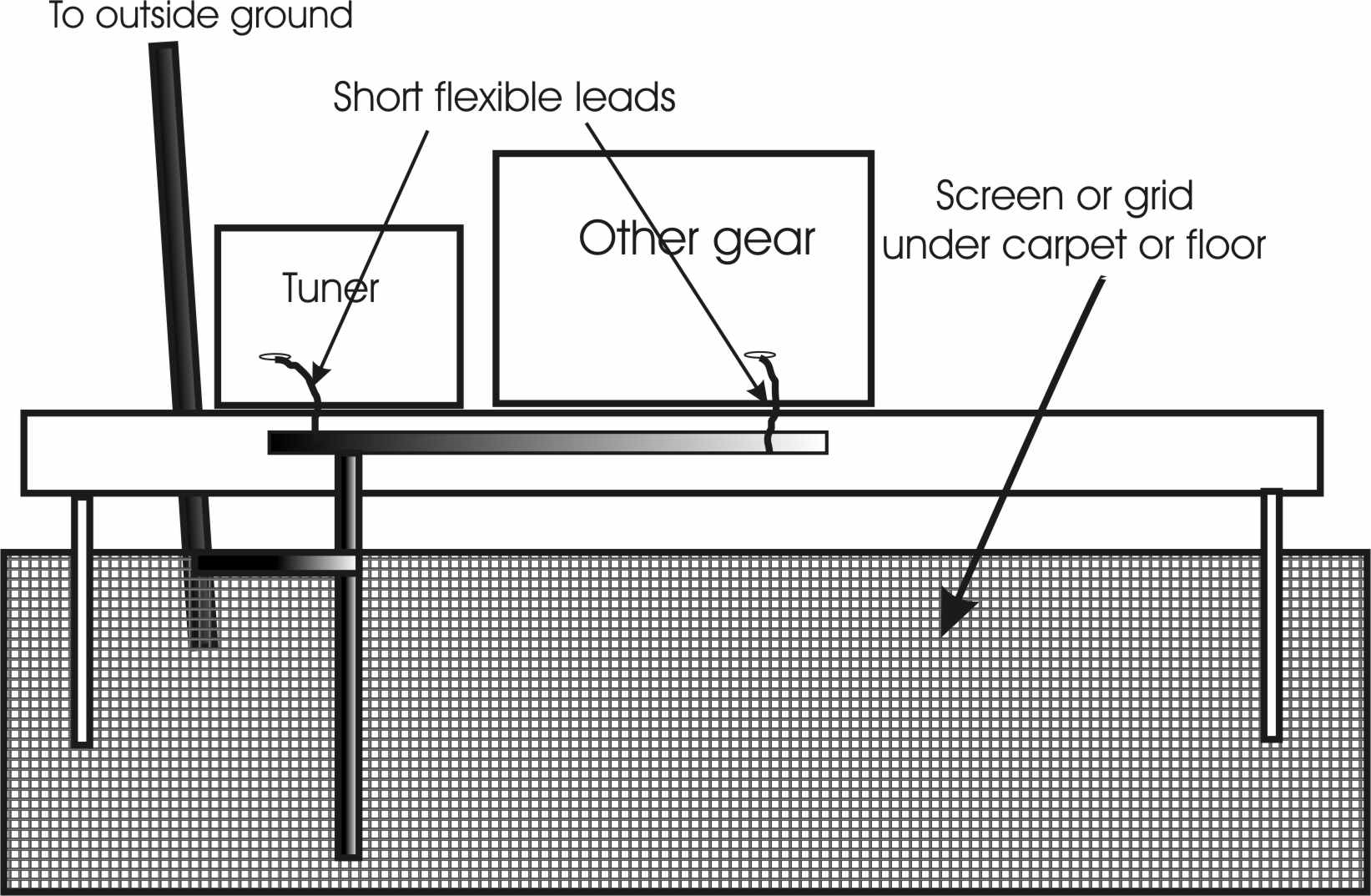
The antenna lead from the tuner "longwire" terminal to the antenna should parallel and be reasonably close to the outside ground lead, if possible. This forms a two-wire transmission line, which helps to reduce external fields. the single wire feeder should be kept away from the operator and RF sensitive equipment. The lead to the longwire antenna should be as short and direct as reasonably possible, because the feed wire is a leaky transmission line.
The grid of foil, metal screen, or wire grid does not need to be too dense. Below 30 MHz, spacing conductors one to two feet apart is nearly as effective as a solid sheet.
If we can't do that, then sometimes a 1/4 wave counterpoise along the baseboard will work. But it is fart better to disperse the current in a widely spread-out path, making all areas of the operating area have similar RF potential without concentrated currents.
Method 2, Keep Problems Outside
The best method of taming a long wire is to install a good low-loss current or choke balun just outside the operating room. This effectively puts distance between the leaky feeder and radiating ground leads outside and away from sensitive equipment.
Basic Simple System
A system like this
is ideal for a minimal investment unobtrusive counterpoise.
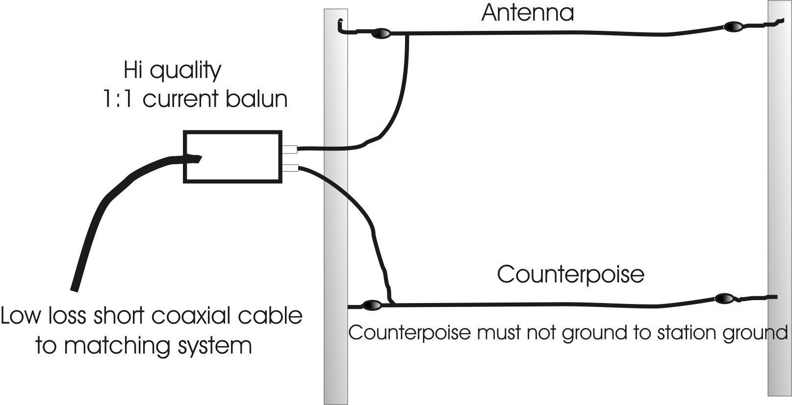
This system, even with a minimal RF ground, keeps common mode currents out of the operating area. This system reduces noise and RFI. It generally eliminates the need for a shack "floor groundplane". The balun must be a reliable current balun with high common mode impedance. A voltage balun, or a single core 4:1 balun, will make things worse.
The counterpoise can be a ground system like radials instead of a single counterpoise. It just cannot connect back to the station entrance ground, or the balun's ground. If it is a single wire or a few wires, they should be insulated from earth and kept a little distance above earth. Ideally the single wire counterpoise should be directly under the longwire antenna, and a few feet above earth. Remember the counterpoise will have considerable current and voltage, and might be an RF burn or shock hazard.
Because a counterpoise is less than perfect, and can even have a fairly high impedance on some bands, the counterpoise system will try to "ground" back through the station gear. Unun's and voltage baluns have a low impedance path for common mode currents, and will not isolate counterpoise currents from the shack equipment. A current balun isolates the ground path from the counterpoise to the shack. The balun must be a high quality current balun, not an unun or voltage balun. It should be a 1:1 ratio with high common mode impedance and high voltage breakdown. The coaxial feed line, since it operates at high SWR, should be high quality and as short as possible.
Ideally the counterpoise wire should be elevated above earth. This minimizes earth losses, and the counterpoise should not be connected to a ground rod or especially to the station ground. The required lightning and safety grounds must all be on the coaxial side of the balun. Unless the ground system is nearly perfect with near-zero RF impedance, it is best to keep the antenna's ground or counterpoise isolated from the feed line shield and station equipment.
Improving the System Above
At the expense of simplicity, a better ground will improve efficiency. A better ground would be multiple radials, or multiple counterpoise wires. The ideal system, in which efficiency would nearly equal that of a balanced center-fed system, would be a ground system similar to radials for a vertical. The ground system can include existing wire fences or metal plumbing, or might be a totally new system installed just for the antenna. A good enough ground system, or large area counterpoise system, reduces RF voltage on the ground terminal. If the voltage on the counterpoise or radial ground system is large enough to present a low impedance, station equipment and the antenna ground systems can be tied together. Isolation, such as a current balun, might not be required. The counterpoise, in effect, becomes "less hot" with RF voltage.
Such a system would minimize RFI and electrical noise problems. With a large system of multiple wires, current density in lossy earth surrounding the radials is reduced.
One common misconception is a near-perfect ground needs 120 quarter-wave or half-wave radials. This is not true. Even 15-20 radials can form a very low loss ground. All we can do is install the best ground we can manage. The more wires used in a counterpoise or ground, and the more spread out the conductors are, the less critical and frequency sensitive the system becomes. The point of diminishing returns is generally around 15-25 radials. If 40-60 reasonably long radials are used, any further increase becomes meaningless. A semicircle of 10-20 radials radiating outward from the feedpoint, generally following the antenna direction, is usually good enough to make further work a waste of time. The best systems would center equally on each side of the antenna, if possible. Small systems should be suspended above ground, if possible, to minimize losses.
For more about end-feed systems follow the end-of-page links: