Receiving Antennas
A better receiving antenna can only come from three things:
1.) Reducing common mode noise. Common mode noise is from an antenna being
electrically "wired", or connected, to noise sources. This occurs even if the
connection is an indirect path we cannot easily understand. It is caused by poor
antenna to feedpoint interface, a bad feed line or connection, or a poor antenna
design.
2.) Altering and reducing near field coupling. If an antenna is near noise
sources, or conductors radiating noise from noise sources some distance away,
the near field response of an antenna can be important. The field impedance of
an antenna, or the ratio of magnetic to electric fields, varies with distance
and position with any antenna. There isn't any antenna that is purely electric
or purely magnetic, and even if there was there is no noise source that is
purely electric or magnetic. Some antennas, just through luck, might couple less
to very close noise radiators. At a relatively small distance every antenna
works the same so far as ratio of magnetic to electric fields!
3.) Directivity, or the antenna pattern, can reduce noise. An antenna does this by being more sensitive in the direction or polarization of desired signals, and less sensitive in the direction or at the polarization of noise.
With any low-height receiving antenna, like an EWE, K9AY, loop, or Beverage, the antenna responds to vertically polarized signals! Even a long, low, horizontal wire, like a Beverage, is a vertically polarized receiving antenna.
Keep all of this in mind, as you look at antenna choices.
Receiving Antenna Design
Dynamic Range and Sensitivity
160 meters is almost always the worse band for ambient noise, as compared to signal strength. Of course each location varies. Just how far above atmospheric noise floor are 160 meter signals?
My local wintertime 350Hz BW noise, compared to a sample of signals, (on one night) was:
| Noise | -127dBm | miles |
| 9H1BM | -122dBm | 5400 miles |
| OM0WR |
-95dBm |
5100 miles |
| DF2PY | -88dBm | 4600 miles |
| WA8OLN | -78dBm | 650 miles |
| W3GH | -60dBm | 650 miles |
| W1AW | -53dBm | 900 miles |
| W4ZV | -32dBm | 400 miles |
The above signal levels may not be typical of every night, but they show the large signal level variations between weak DX and strong one-hop signals.
The signal level difference between noise floor and W4ZV was 95dB. W1AW and W4ZV, both in similar directions and both with similar power, have a difference of 21 dB. This is over 100 times difference in power levels at my receiver. This illustrates how important the combination of antennas, location, and propagation (W4ZV is one sharp hop away) are, rather than power, location, or antennas alone. Differences between signals from the same area can be quite pronounced.
Before talking about receiving antennas for lower frequencies, it is important to understand a few basics. We all understand the primary reason we use special receiving antenna systems is to improve signal-to-noise ratio. On the surface this sounds like the same reason we use directional transmitting antennas, but there are some very important differences between transmitting and receiving applications.
Reciprocity
We often hear a 7dBd gain Yagi will improve receiving by a similar amount over a dipole. People are told to invest in a good transmitting antenna and low-loss feed line, because it makes both transmission and reception better by the same amount. The logic behind this claim is that because of reciprocity,gain works the same on receiving as on transmitting.
On the surface this sounds reasonable, but it is not actually correct in most (if not all) cases! A 7dBd gain antenna with 20 dB nulls can improve receiving any amount from no improvement at all, up to 30 dB or more, depending on many things we often don't consider.
Transmitting
While transmitting, we cannot tolerate significant power loss. The most important antenna characteristic, other than a reasonable SWR and having the antenna remain in the air for a while, is having maximum possible field strength in a given direction or directions. In general, the single most important transmitting parameter is having maximum gain in all desired directions, and maximum gain over the range of most useful waveangles. For a given polarization and wave angle, the highest gain antenna will deliver the strongest signal to our target area.
Transmitting antenna choice is reasonably simple, we want the maximum possible properly positioned gain. Take-off angle, side-lobe strength, and F/B ratio take a back seat to maximum gain at the desired wave angle and direction. We can generally model the antenna and confirm the results with a few simple measurements, and be confident we have made a good choice. Take-off angle is not important. We need maximum possible gain at the desired angle and direction. We don't care where the peak is, so long as the transmitting antenna we use has more signal (gain) at the desired angle and direction than other antenna choices!
Receiving
For optimum receiving, the antenna system has a different design goal. Gain can totally mislead us. So long as the receiving system is limiting on external noise picked up by the antenna, gain is not important at all. The only parameter that matters while receiving, so long as the system is hearing outside noise, is directivity. Directivity is different than gain, because directivity does not include any consideration of efficiency. This is why, even in a quiet location, I can use thousands of feet of RG-11 coax on a zero dB gain antenna, and still be limited by atmospheric noise propagated from hundreds and thousands of miles away.
If you would like to hear a demonstration of how excellent directivity reduces noise, listen to QRN_JA2ZJW on the DX Signal Recording page.
I'll go over all this again in more detail below....
Antennas and Fields
If we are going to pick the best receiving antenna, it is important we understand how antennas respond to "signals" and "noise". Unfortunately, this is probably the single most misunderstood part of receiving antenna design. This a problem mostly because we are constantly bombarded with folklore giving us the wrong impression of how antennas work.
One example that comes to mind is small loops, often referred to as "magnetic radiators". Folklore often considers the radiation or response of these antennas as somewhat magical, with the antenna behaving like a sieve that sorts "good magnetic signals" from "bad electrical noise". Nothing is further from the truth! At a relatively small distance the small magnetic loop is more sensitive to electric fields than a small electric field probe. The ratio of electric to magnetic fields are sometimes called the "field impedance" of the antenna. An antenna with a high field impedance has a dominant electric field, and an antenna with a low field impedance has a dominant magnetic field, when both are compared to freespace ratios at a large distance from the antenna.
At distances of about l/2, the field impedances of all by physically large antennas are almost indistinguishable from each other, no matter what the antenna type. Strange things happen at closer distances, as we will soon see. Once we understand the basics, we might picture our antennas differently. We might find antennas don't respond to signals and noise like we thought, but at least we won't be as susceptible to the "noise" caused by rumors and folklore!
Induction field
The induction-field area involves the energy storage area around the antenna, and involves both electric and magnetic fields. These energy storage fields dominate the system near the antenna, although the radiation still exists. Contrary to some bizarre claims (i.e. CFA or CTHA Antennas), there is no possible way to "mix" induction fields and create a radiation field. The effects that cause each are different, and they follow different rules. The induction fields fall off much more rapidly with distance than radiation does, even though we "measure" or talk about each in terms of magnetic and electric effects.
We can move the fields around, concentrate them or spread them out, and even change the ratio of these fields...but every antenna has both electric and magnetic induction fields. Whenever we have a time-varying electric field, it must be accompanied by a time-varying magnetic field.
We might consider induction fields part of direct capacitive or inductive coupling between areas of the antenna and objects or space around the antenna. Close to the antenna, field intensity might not fall off as the rules normally predict with distance. Very near an antenna, fields are an accumulation of effects from sources at multiple directions and distances. It isn't always easy to understand what actually is happening very near an antenna, where the area of the antenna is large compared to the distance where we are observing the effects. Near the antenna, pattern and field impedance is generally nothing like we might intuitively imagine.
It is the response in this area, generally within l/10 distance from the antenna, that small "magnetic loop" and "electric dipole" antennas get their names.
Very close to a small loop antenna (but not necessarily very near the open ends), the magnetic field dominates. We could describe that effect by saying say the field impedance is "low". Conversely, near a small dipole or monopole the electric field dominates, the antenna has a high field impedance. Remember, this generally applies only with l/10 distance from the antenna.
The since the distance of a wavelength in the above graph (thanks W7EL) is 100 meters, we can also considered the bottom scale as a percentage of a wavelength. We can see at about 11 percent of a wavelength (which would be about 50 feet on 160 meters), there is no difference in field impedance between a small loop and a small dipole. At distances beyond 50 on 160 meters, the loop actually has a higher field impedance than a dipole.
So much for the myth that a receiving antenna can sort good signals from bad signals (noise) by virtue of being "magnetic"! We not only don't have the response we might imagine, we probably have no idea if the close-by unwanted signal source is radiated from a source that is electric or magnetic field dominant. Successful noise reduction by virtue of by antenna "style" would mostly be a matter of hitting a lucky combination through careful experimentation.
Near Field
The near field area is an area where the ultimate pattern is not fully formed. It is possible, with large arrays of small elements, to be out of the induction field region but still well within the near field area. Let's consider individual groups of elements as "cells", and the array a combination of small directional cells occupying a very large physical area.
This occurs in some of my broadside/end-fire combination arrays because physically small antennas forming individual end-fire cells are combined forming an array more than one wavelength across. The array is physically large, and at a distances of several wavelengths the combined field clearly originates from multiple sources that vary in distance or direction. The pattern is not perfectly formed because the signal from closer elements is less attenuated by distance, and the phase difference between the cells at a given azimuth is not the same as the ultimate phase further away at the same azimuth.
This applies to utility line radiation, where distant noise sources are conducted along the entire line. To the receiving array, it might appear that a single arc on an insulator a mile away is actually radiating from multiple directions with many phase relationships. The field the receiving antenna "sees" might appear to arrive from multiple directions, making it difficult or impossible to null the noise with a simple directional cell or more complicated array of directional cells. This would be a good application for a device like an antenna noise canceller, because the noise at the antenna terminals will be the vector sum of response to multiple radiated fields reaching the receiving antenna from a single noise source. In this situation a sample of noise taken near the power line could be combined out-of-phase with the sum of radiation points along the power line to null the noise.
Clearly a noise source or sources might also be outside the induction-field dominant area, and still not have a fully formed pattern. Antennas must be in the far field of the noise source, and the noise source must be in the far field of the antenna if patterns are to be predictable when nulling noise. Besides the fact larger distances provide greater attenuation of noise, it is also very desirable to locate our receiving antennas in the far field of noise sources, and noise sources in the far field of the antenna. This makes a good case for placing receiving antennas as far from other conductors (such as power lines) as possible.
This doesn't means urban or suburban dwellers should give up and move to rural areas, it just means the results will be less predictable and actual experimentation is likely required. Results aren't always predictable, unless the antenna is a few wavelengths from other potential unwanted signal radiators or objects that might affect antenna pattern.
Noise
The noise that limits our ability to hear a weak signal on the lower bands is almost always an accumulation of many signal sources. Below 18 MHz, the noise we hear on our receivers ( even at the quietest sites) comes from terrestrial sources. Receiver noise is generally a mixture of local groundwave and ionosphere propagated noise sources, although some of us suffer with dominant noise sources located very close to our antennas.
Our locations fall into three basic "radio" categories that may or may not be related to our actual communities:
Note: noise levels quoted in this text are the average of three independent studies by Bell Labs, FCC Land Mobile Advisory committee, and the Institute for Telecommunication Sciences. Rural data are actual measurements of summer noontime and winter midnight noise at my location, several miles from high voltage transmission lines and far from any industrial or suburban populations.
Urban
In urban-type noise situations, noise arrives from multiple random sources through direct and groundwave propagation from local sources. One or more sources can actually be the induction-field zone of our antennas (in most cases the induction field dominates at distances less than 1/2l). Urban locations are the least desirable locations because typical noise floors average 16dB higher than suburban locations. There is often no evidence of winter night noise increase on 160 meters, since ionosphere-propagated noises are swamped out by the combined noise power of multiple local noise sources. Much of the noise sources are utility distribution lines, because of the large amount of hardware required to serve multiple users. Other noise sources are switching power supplies, arcing signs, and other unintentional man-made noise transmitters.
Suburban
Suburban locations average about 16 dB quieter than urban locations, and are about 20 dB noisier than rural locations. Noise generally is directional, arriving mostly from areas of densest population or the most noise-offensive power lines. Utility high-voltage transmission lines are often problematic at distances greater than a mile, and occasionally distribution lines can be problems. The recent influx of computers and switching power supplies has added a new dimension to suburban noise.
There is often a small increase in nighttime winter noise at exceptionally quiet suburban locations. This increase occurs when propagated terrestrial noise equals or exceeds local noise sources.
Rural
Rural locations, especially those miles from any population center, offer the quietest environment for low-band receiving. Daytime 160 meter noise levels are typically around 35-50 dB quieter than urban, more than 20 dB quieter than suburban locations. Nighttime brings a dramatic increase in low-band noise, as noise propagates in via the ionosphere from multiple distant sources.
Primary local noise sources are electric fences, switching power supplies, and utility lines. I can measure a 3 to 5dB daytime noise increase in the direction of two population centers, Barnesville (population 7500, distance 6 miles) and Forsyth (population 10,000, distance 6 miles) Georgia.
Typical daytime noise levels, measured on a 200 foot omni-directional vertical, are around -130 dBm with a 350 Hz bandwidth (noise power is directly proportional to receiver bandwidth) . Noise power increases about 5 to15 dB at night, when the band "opens". As in the case of suburban systems, directional antennas reduce noise power.
Nighttime is the "big equalizer", reducing the advantage of location as distant noises increase with improved propagation.
How Important is Gain?
When choosing one receiving antenna over another, never select an antenna by comparing antenna gain. Gain only affects receiving performance when the receiving system noise floor is determined by internal system noise. If we hear a definite decrease in noise when replacing the antenna with a dummy load of the same impedance, gain by itself is not a factor.
Noise not only varies with the hour of day, it also varies with direction and season. Further complicating matters, noise power is directly proportion to receiver bandwidth. Going from a 2.5kHz filter to a 250 Hz filter with the same basic shape-factor reduces noise by 10 dB. When determining if system gain (for a given directivity) is adequate to establish system noise floor, tests must be made at the quietest operating time using the narrowest selectivity. In general, we should set system gain to allow a comfortable increase in noise when the antenna is connected at a time when propagation is poor but adequate to allow some contacts. This sometimes results in excessive gain when propagation is more favorable, but it is simple to remove gain (either by adding an attenuator or removing an amplifier) when using wider bandwidths or if conditions are noisier.
My receiving antennas have high dynamic range amplifiers using push-pull 2N5109 transistors. Amplifier gain is approximately 15 dB, and noise figure is approximately 5 dB. Gain compression occurs at approximately 30 dBm (1 watt) output. The blocking dynamic range of the amplifiers (using a 250 Hz bandwidth on the receiver) is around 180 dB, making my receivers the limiting factor. The amplifiers have internal bypass relays, allowing them to be easily bypassed when required by removing amplifier power.
Each of these amplifiers drives a four-way splitter, allowing any one-of-four receivers to connect to any antenna. Multiple receivers can select the same antenna simultaneously. Splitter system loss is 7 dB. Typical net system gain is around 8 dB to each receiver. Some amplifiers are designed to have slightly more gain and some less gain, because some antenna systems have a lower noise floor than others.
What Antenna Parameter is Important?
Once any receiving system limits on external noise, antenna pattern becomes the only thing that matters. Here are the patterns of two Beverage antenna systems, each with different gains. One antenna uses two side-by-side Beverages, while the other is a single Beverage. I'll include Eznec wire tables so you can model the antennas, and see the mistake we often make.
First, the wire table can look like this:
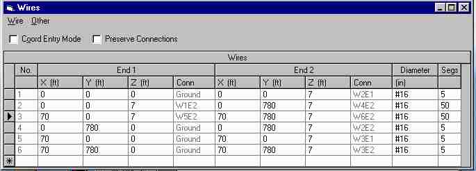
This is two Beverages 70-feet apart. If we terminate both of them and set the source of one at zero (so only one Beverage is active), the following pattern results:
Now we add the second source, so both parallel Beverages are active. The pattern and gain is now:
Gain is now -8.2dBi, about 3 dB better than the single wire's -11.24dBi. Did we gain any signal/noise ratio, for all the work of adding a second antenna?
Not a bit...the S/N ratio is exactly the same because the directivity is the same. Since unwanted noise is external to the antenna, unless we have a change in pattern we can not have a change in S/N ratio. It is a common mistake, and absolutely incorrect, to compare gain and use gain to estimate receiving ability.
Eznec version 3.0 allows us to estimate directivity by modeling the antenna in three dimensions, and looking at the pattern. Here is the first Beverage modeled that way:
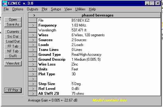
One source is set to 0 amperes, turning off one wire. Notice the "Average Gain" that appears in the lower area, -22.67 dB. If we subtract the average gain from the -11.24dBi gain at 20 degrees, we will have the ratio of response in the desired direction (from a two dimensional plot) to the overall gain of the antenna. This will be a positive number. The result is what we can consider a "receiving directivity factor" of the antenna expressed in dB. In this case, the RPF is 11.43dB.
Now let's look at the two wire antenna, using the same method:
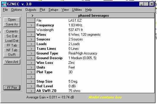
Notice I modeled this with both sources at 1 ampere, so both Beverages are active. Using the same process we used for the single source (which was the same as only having one Beverage) we see the RDF at 20 degrees is now (-8.2)-(-19.74) = 11.54db!
The effective receiving performance only increased 0.11dB, not worth the effort of adding a second antenna!
Changing spacing to 350 feet, we have the following two-dimensional pattern:
.....and the following data in the main menu of Eznec after modeling a three dimension plot.....
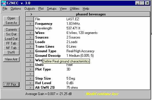
Taking (-7.44)-(-21.25) we now have a RDF of 13.81dB at a wave angle of 20 degrees. Comparing the three systems:
| Antenna | Gain @ desired elev & azmth | Average gain | Rcvg Directivity Factor |
| single Beverage | -11.24dBi | -22.67dB | 11.43dB |
| 70 ft spaced Beverages | -8.2dBi | -19.74dB | 11.54dB (+.11dB RDF) |
| 350 ft spaced Beverages | -7.44dBi | -21.25dB | 13.81dB (+2.38dB RDF) |
Summary
Until Eznec's Windows version came along, it was very difficult to estimate performance. We often made mistakes, because we only compared gain. Using the above method, we can estimate antenna performance for evenly distributed noise. If there is no change in the Receiving Directivity Factor for similar pattern antennas, we can be sure we haven't changed overall performance for distant signal and noise sources.
There are a few things we have to keep in mind:
1.) If noise is not evenly distributed (which is often the case) performance will depend on the gain difference between desired signal direction (azimuth and elevation) to gain in the direction of noise(s). A 20dB null on the noise compared to gain in the desired signal direction will actually improve S/N ratio by 20 dB, if the noise from the null direction totally dominates all other noises.
2.) If noise arrives primarily from the same direction and angle as the desired signal (and assuming polarization of signals and noise is the same), there will be no S/N improvement.
3.) If noise originates in the near field of the antenna, all bets are off. Anything can happen.
All in all, the above method gives us a rough idea how various antennas compare in a environment with reasonably even noise distribution.