Related Pages
This page deals with the entire system, including radio RF output.
In radio systems, especially when multiple devices are connected, the sequence of events is critical. Some radios have inherent RF output to external relay control timing issues. The result of improper timing is often a very wide leading edge "pop" or "click". The pop or click repeats at every relay closure. Slow VOX or semi-break in causes less frequent pops than QSK or fast VOX operation.
The system sequence is:
Some radios are terrible for RF sequencing. There are some radios that actually output RF before telling external devices RF is going to appear. There are other radios that continue to output RF after they tell external devices to go back to receive. This is a radio design problem! It is bad radio circuit engineering.
Most small to medium relays for amplifier switching require 5-15 milliseconds to transfer and stop contact "bouncing", with small enclosed and vacuum relays running around 5mS. Typical larger open-frame relays are in the 10-20mS time range.
PIN Diode switches can close and open in a few milliseconds or less.
Some very small reed relays rival PIN diodes in time. There are some low-power reed relays that operate in less than 1mS!
The most common errors are:
Measurement of time delay requires a dual channel oscilloscope with separate trigger input, and a low frequency signal generator.
I normally use this keying test setup:
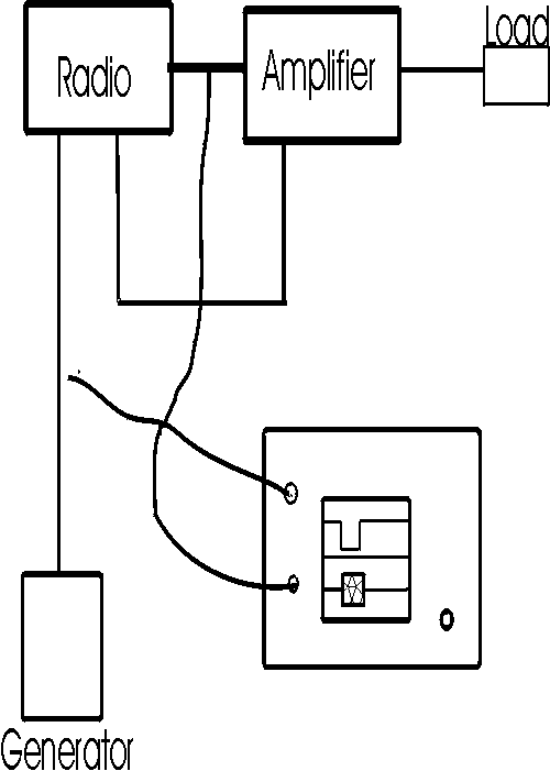
The radio must have enough RF output delay AFTER the radio low-amplifier control signal appears so the amplifier relay does not truncate leading edge of RF
The radio or amplifier must hold the relay long enough so the falling edge is not truncated.
Some systems have multiple control lines from different devices that must be "keyed" in parallel. With direct parallel connections, one device can load the system and stop other devices from operating properly. This usually happens when a device is off but still connected. Simple isolation diodes work to prevent that, but the voltage and current at the radio is the highest voltage of any device and current is the sum of all the device currents. Even worse, the radio output control has to discharge the RF bypass capacitors of each connected device.
My 160 station consists of a solid-state homebrew amplifier with 16 MRF-150's, an AL1200, an 8877 amplifier and either an FT1000D or an Orion. I almost never listen through the FT1000 or Orion when working CW, so I also have at least two outboard receivers that must be muted.
My homebrew 8877 amplifier uses a high-voltage relay system, the solid state amplifier has 5-volt TTL level switching, the TX antenna sampling line uses a 28-volt vacuum relay, and the receivers have 5 volt muting lines that mute when pulled to ground. The Ten-Tec Orion requires an isolation relay on the receive antenna port, and I occasionally switch other devices when transmitting.
All of this is driven by a microprocessor controlled antenna switching system that prevents changing antenna directions or antenna while transmitting.
Any attempt to directly parallel devices would be a disaster!
The circuit below interfaces my radio to multiple amplifiers, receivers, and antenna control systems. Multiple devices can be connected in parallel, such as 28 volt relay control lines and 5 volt control lines, as long as they are all positive voltage. This system pulls within 1 volt of ground.
It is necessary to be careful with some radios. There is no standard interface voltage. TenTec, for example, uses interface systems that have a threshold around 1 volt. TenTec's handshake lines require buffering with a small very fast reed relay, many transistors and IC's will not pull low enough to activate the TT handshake line. If you need relays of any type between the amplifier keying system and the radio, always be sure you test the entire system for proper relay sequencing.
RadioAmp goes to radio's amplifier keying control output.
EXTcon goes to computer or other keying device that only handles low-voltage low-current.
D2-D6 go to devices that require control.
+5V sets the threshold of EXTcon trigger. EXTcon open circuit voltage is also limited to less than 5 volts.
The radio is exposed to the highest voltage from the keyed loads, but the current is limited to roughly V/500 where V is highest voltage device. A 28 volt amplifier would require the radio to key about 14mA peak current during relay transition, although average current would be lower. The exact current depends on beta of Q2 and Q4, and if EXTcon is used. A device like Q6 can be added to the radio line to limit radio voltage to 5 volts or less regardless of amplifier relay voltages.