Related pages:
One of the biggest issues is trying to use too much inductance in a wide
operating frequency range plate choke. Physically large chokes over 50-100 uH
almost always develop low impedance resonances someplace in HF. Choke
physical size and choke inductance are the determinants. More inductance
moves unwanted resonances lower. More distributed capacitance to the outside
world does the same. It is the combination of shunt capacitance to the outside
world and choke inductance that creates the problem.
Chokes and large
inductors (including roller inductors in antenna tuners) should be tested or
measured for series resonances. Ideally test setups would emulate the final
choke, trap, or inductor stay capacitance caused by the final mounting and
surroundings.
There are two accurate methods to determine resonances of a plate choke, inductor, or trap. The first simple method uses minimal equipment and can give very accurate relative go/no-go results.
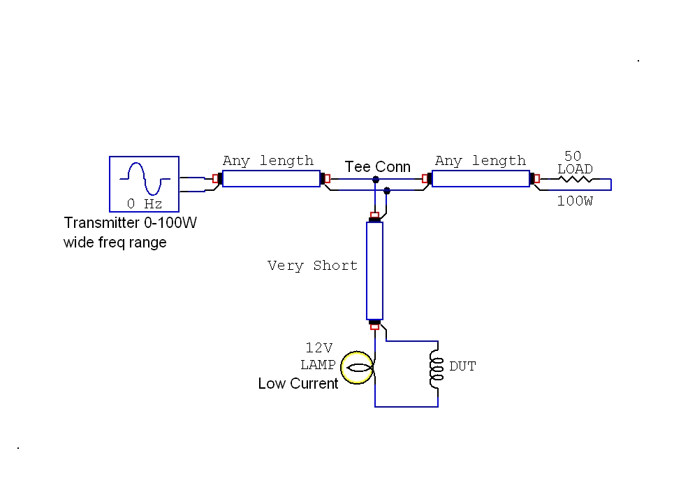
This method uses a transmitter or transceiver covering the operating range, dummy load, T-connector, and a series incandescent lamp indicator.
1.) Minimum brightness trap (or parallel) resonance. Maximum brightness unwanted choke series resonance.
2.) Use a calibrated RF impedance measuring device with transmission line normalized out

1.) Trap test, try to keep the trap in open air and minimize stray capacitance. Stray capacitance affects resonance.
2.) Choke test, try to space choke the same distance from ground plane as it is from closest mounting box wall. Wall spacing affects resoance.
Note: It is only possible to get close without
special fixtures!
An amplifier's plate choke needs a certain minimum impedance throughout the amplifier's operating frequency range. Let's consider a typical pi-network amplifier.
The minimum required plate choke impedance varies with the operating impedance of the output device, the choke's Q or loss resistances, and compensating capacitance available in the tank tuning capacitor. The RF plate choke must have several thousands of ohms when the amplifier uses high voltage tubes. RF plate choke impedance must be high enough to limit RF choke current to safe values. A conservative RF current estimate would be E/Z=I where E is DC plate voltage and Z is choke impedance. A 200 uH choke on 1.8 MHz only has about 2600 ohms reactance, so a 3000 volt anode swing causes 1.15 amperes peak RF current. RF choke dissipation would be choke Erms^2 / Rp. A 200uH choke with a Q of 40 would dissipate something less than 2100^2 / 104000 = 42 watts.
42 watts is significant power, although perfectly acceptable in a single layer ceramic form choke of fairly large dimension. The very high Q requirements and the large RF currents illustrate why iron core or ferrite core chokes are generally unacceptable at high anode voltages, and why the general trend is to use physically large solenoid chokes on low loss high temperature forms. A second design issue appears. As frequency increases, choke impedance increases. At some frequency choke impedance will peak. Significantly above peak impedance, choke impedance will abruptly drop. This effect becomes a real problem in 160-10 meter amplifiers. A choke adequate for 160 meters in high operating voltage use develops unwanted series resonances someplace up above lower-to-middle HF.
Series Resonances
Series resonances produce very low choke impedance. This is accompanied by very high RF voltages from the choke to the choke ends and to the outside world. I've seen chokes arc across several inches of air in amplifiers operating at 6-8 kV supply voltage.
Series resonances are formed when the choke looks like back-to-back L-networks. The choke winding forms a long series inductance and stray capacitance tunes the winding. This of course could be viewed as a long helical transmission line of very high impedance, but L networks provide a closer if not significantly less complex analogy. Electrically, at the lowest frequency series-resonant point, the choke looks like this:
Fig 1
The SPICE sweep model below shows voltage at point A.
This model very closely approximates an early Ameritron plate choke. This is why 26-27 MHz operation generally destroys an Ameritron choke.
This model is with 200 volts peak-to-peak excitation, NOT the full voltage of the amplifier. The waveform below shows RF current through the choke. DC current is not shown, and would be superimposed on the RF current. 10 volts=1 ampere:
Ever wonder why an amplifier can arc and bang when operated near self-resonance of the plate choke? The text above should explain it to you! Voltage at the center of the choke can be so high the choke arcs for several inches. The choke becomes a good Tesla coil, with peak RF voltage near the coil's middle for the first-order resonance.
At upper frequency limits, a typical choke can have peak voltages several times the operating dc voltage at some points along the windings. Stray capacitances also tend to concentrate RF currents into small areas of the winding. Because stray capacitance aggravates voltage and current stresses, and because stray capacitance shifts series-resonances lower in frequency, a clear location for the choke is most desirable. If possible, a choke should be 1/2 its winding length, or four times the winding diameter, away from things that add capacitance. This includes large dielectrics, which increase stray capacitances from increased dielectric factor loading of electric fields.
Choke designs require a certain minimum inductance, to ensure reasonable impedance near lower frequency limits. If the choke is physically large, and if reactance is fairly large at the lowest frequency, and if a wide frequency range is covered, unwanted series-resonances can fall within desired upper operating ranges. This can result in very high currents and voltages from normal fundamental RF excitation, although it is sometimes blamed on a "parasitic" by less knowledgeable designers or technicians. The solution is to move undesired series-resonances outside desired frequency ranges.
Many publications, including the ARRL Handbook, and many personal opinions, claim choke winding gap designs are "magic". At one time, the ARRL Handbook reported there was no rational, logical, reasoning behind removing sections of solenoid choke windings. This is not true, and really only shows those who make such statements do not understand why a choke has series resonances, or how to move the resonances. If we understand why a choke misbehaves on some frequencies, we will easily understand how to "correct" problems in the RF choke by using gapped windings. There actually is a method to designing choke winding gaps. Since the series-resonance problem is rooted in the choke behaving like two (or multiples of two) back-to-back L-networks, the solution is very obvious.
When moving unwanted series-resonances, the system's necessary minimum inductance often rules out significant inductance reductions. Turns must be added or removed where they have the largest effect on series resonances, with minimal reduction of lower frequency inductance. To do this, the designer must find the highest voltage area of the winding at the problematic frequency, and reduce capacitance at that physical point in the winding.
The capacitance involved in the series resonance is generally on the order of a few picofarads, or less. The designer generally does not want to locate the choke center near metal (or even dielectrics other than air) because metallic masses, or even dielectrics other than air, will move series resonances lower in frequency.
Generally, the designer wants to do everything possible to move series resonances upwards in frequency, keeping as many high-order resonances as possible above the highest operating frequency.
The most expedient way to move series resonances is to change the winding pitch at the very center of the choke for lowest resonance, or in the electric field's "hottest" winding areas, in the case of higher-order resonances. A typical solenoid choke of constant pitch has capacitance controlling the lowest resonance located in the very middle of the winding length. This is area where inductances, forming the two phantom back-to-back L-networks, are evenly distributed in both directions. At this inductive center-point, just one or two picofarads of capacitance can move the series resonance as much as 50% in frequency! The exact amount of movement depends on winding pitch, form diameter, and the overall inductance of the choke.
The gaps in the Ameritron chokes (or any gapped choke I design) are not placed by accident. The winding gaps are placed by design.
The most effective way to move a resonance is to remove wire from the area where voltage is at maximum.
The 1990's Ameritron choke design appears on the far left. Starting with a continuous winding core, the fully wound choke had resonances at 10 MHz and 20 MHz. Looking at voltage hot spots, sections of windings were removed. The lower gap near the choke middle moved the 10 MHz resonance up to 12.5 MHz or so. This shifted the upper resonance from 20 MHz to near the 24.8 MHz band. The upper gap moved the resulting second-order series-resonance from 25 MHz up to 27 MHz. Without the upper gap, the second overtone resonance is too close to 24.8 MHz. The gaps park unwanted series-resonances between 30 and 20 meters, and at the lower end of 11 meters. This results in the highest possible inductance for 160 meters, while keeping harmful resonances away from normal operating frequencies.
On early solenoid chokes, before we had WARC bands, resonances were more easily parked in clear spots. There was no need to move higher order resonances out of an "overtone" or harmonic relationship with the lowest frequency series resonance. The double gaps reflect a change in choke design from the Heathkit and Ameritron chokes I designed before WARC bands existed.
Variety of winding styles from left to right:
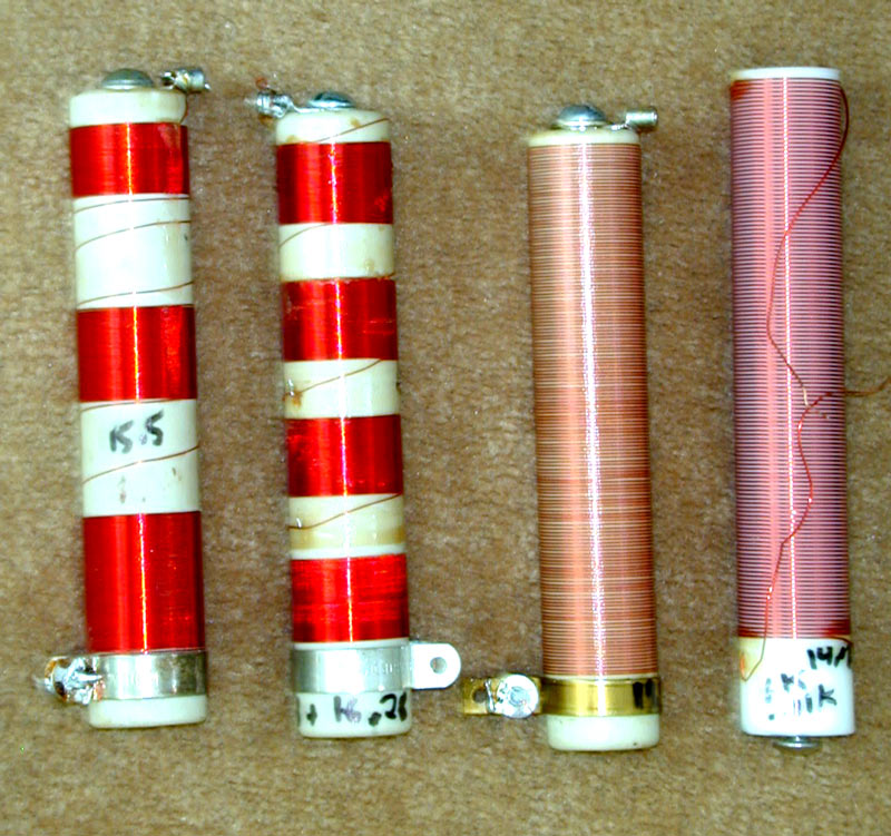
3-unequal section tight wound. 245 µH nominal with resonances at 11.7 and 16.3 MHz.
4-equal section tight wound. 229 µH nominal with resonances at 13 and 16.8 MHz.
Single section space-wound. 117 µH nominal with resonances at 19.5 and 27.3 MHz.
Single section space-wound iron core. 906 µH nominal with resonances at 13.5 and 24.1 MHz. The iron core choke has low Q, and runs much hotter for a given RF current. Series resonances are also very wide, the lower resonance rendering this choke unusable between 13 and 14.5 MHz.
From the above data, we can reasonably conclude an evenly-spaced winding produces the poorest multiple-band high-voltage choke. The choke can have a great deal more inductance by using a tight winding pitch, with harmful resonances moved by intentionally inserting large gaps at appropriate places.
Open air test fixture
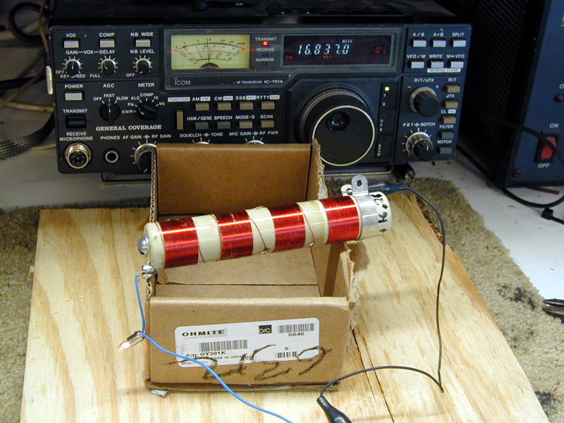
A standard transmitter, dummy load, and 12 volt lamp can be used to effectively test an RF plate choke.
Electrically, keep the transmission line from the "T" connector to the choke and lamp very short. Less than five electrical degrees (one-half foot at upper HF) is generally short enough.
The other two transmission line lengths are not critical.
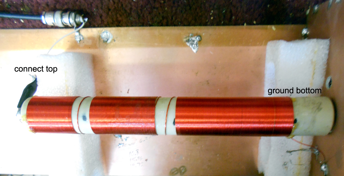
The best place to test any choke is in the actual operating location with the choke cold end bypassed to ground normally. The the top end of the choke should be disconnected from the tank system and tubes, and the tank shorted or detuned so it does not act like a suck out trap. The lamp would go between the disconnected top choke end, and the TL supplying RF. The lead above the lamp to the TL can be somewhat longer, even 5 inches is unlikely to have a large effect. The lead from the lamp to the choke must be short.
Leads from the tap point on the transmission line must be short, as in the bench setup below!
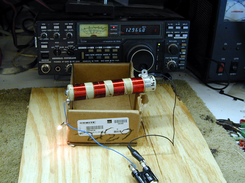
4-section choke under test for series resonance. The transmitter is set at 25 watts and the VFO swept up through the frequency range until the lamp glows. Adjust power so the lamp lights, but does not burn out. In this case series lower resonance was at 12.985 MHz. Moving up from lower HF, this is where the lamp glows brightest.
Spinning the VFO up, we find another resonance around 16.8 MHz.
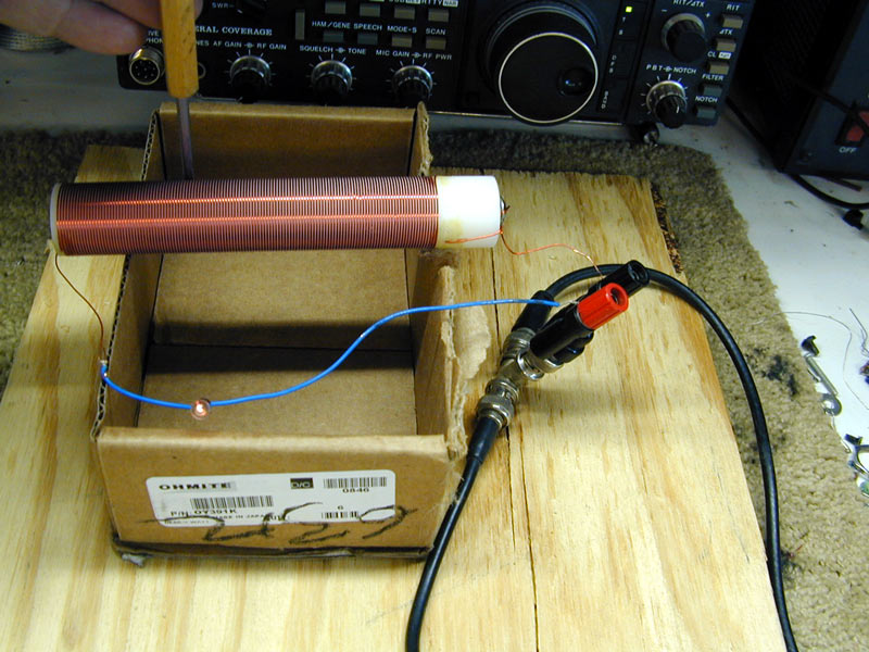
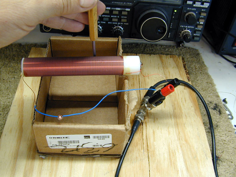
Finding the "hot" area:
The "hot spot" or "hot spots" can be located by sliding a well-insulated metal tipped tool along the choke.
Adjust the radio's frequency to find maximum lamp brightness. Without adjusting the radio, move the insulated tool's metal tip along the choke and watch for the spot where the bulb dims the most. This is the "hot spot" where voltage peaks. If you remove wire in this "hot area", series resonance will shift upward the maximum possible amount for the least change of overall inductance. To lower self resonant frequency, either add dielectric (a thick coating of insulating varnish) or rewind with closer turns spacing.
The higher frequency resonances will be in two or more places out near choke ends. The lowest frequency resonance is always near choke center.
When you find a frequency with the largest hand effect near the center of the choke, you can be pretty sure you have the lowest self-resonant frequency.
When used with proper fixtures, network analyzers provide the most accurate measurements.
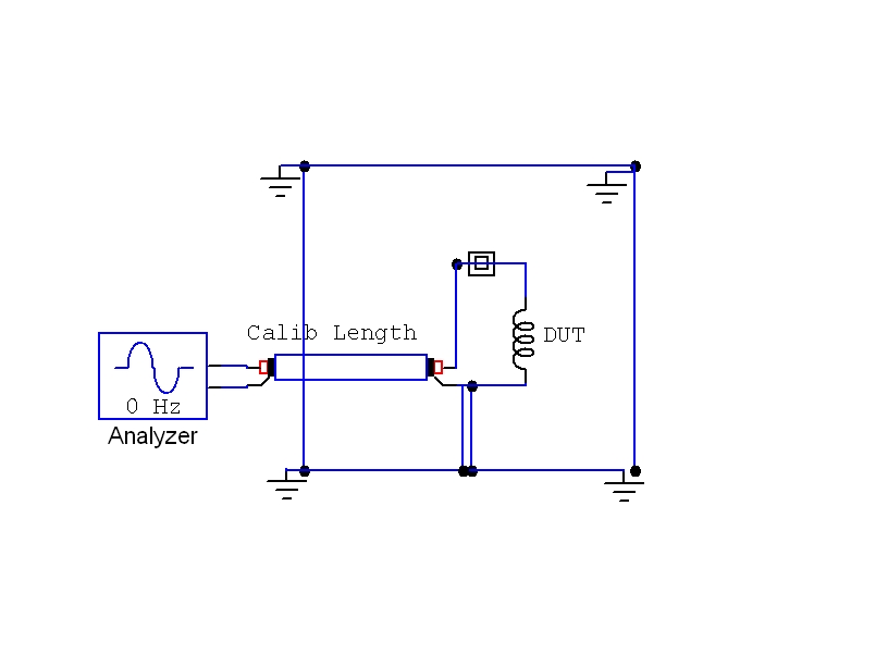
This method also works with traps, although traps should have several inches spacing above the ground plane. Personally, I test traps mounted centered in a three foot copper wall box that is open on one side.
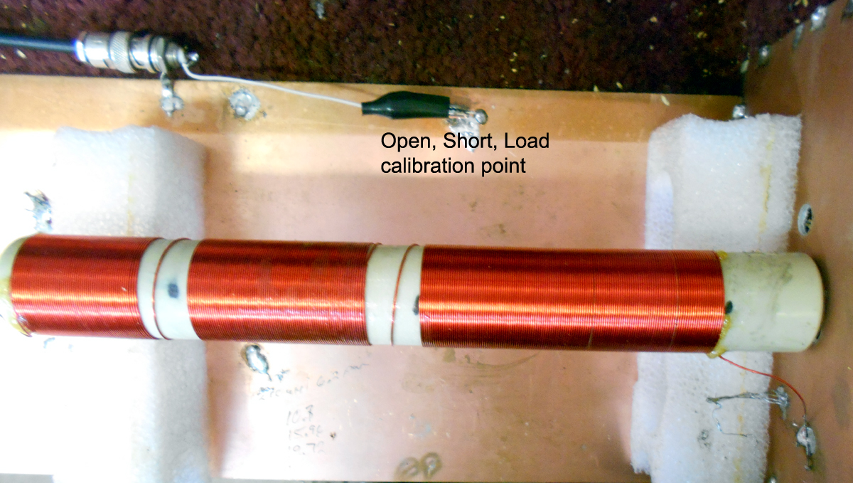
My test fixtures have precision 50-ohm small loads. I can stretch the clip lead out and preform an open, short, and load base calibration.
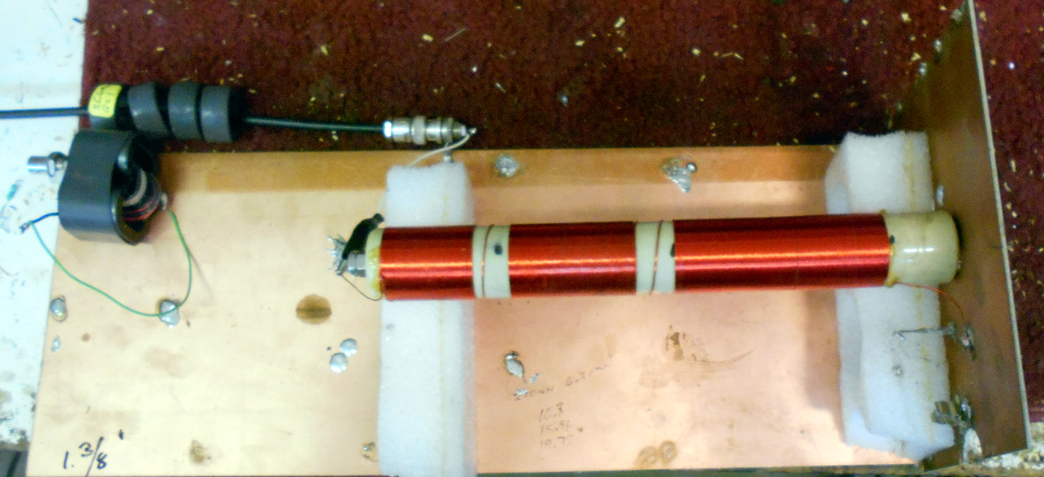
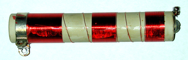
I use a variety of low density foam spacers to hold the choke (or trap). I can easily move the connector to different places. This choke is 13 inches long!
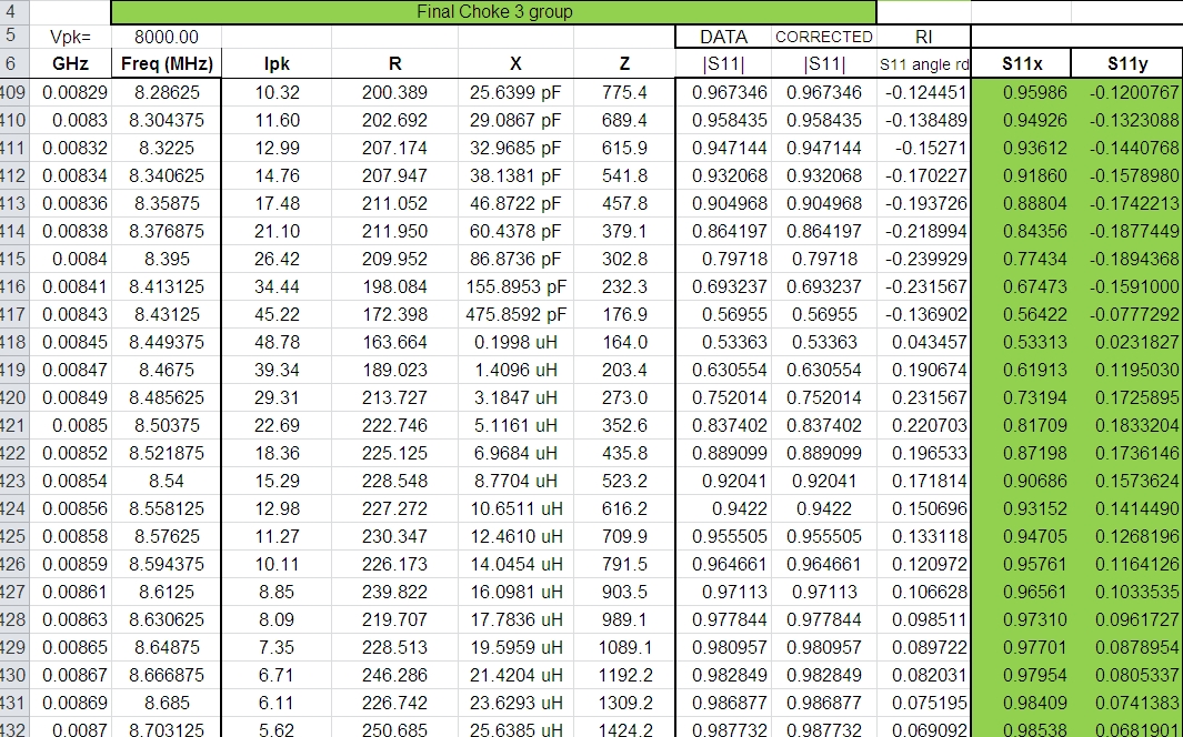
Look at Z. Test results near series resonance are:
The minimum necessary choke inductance in an amplifier or other RF system is dependent on five things:
RF choke impedance varies widely with frequency. At low frequencies the choke looks like an inductor either shunting (parallel equivalent) or in series (series equivalent) with a resistance. Let's look at a Heathkit and Ameritron choke I designed in the late 1980's.
This choke has the following characteristics (from an Excel spreadsheet I used in AL80B design work):
| F MHz | L or C | Xs | Rs | Xp | Rp | Q |
| 1.8 | 255 µH | 2550 | 22 | 2550 | 295590 | 116 |
| 3.5 | 275 µH | 6060 | 85 | 6061 | 432127 | 71 |
| 7 | .36 pF | -315000 | 3851 | -327203 | 26764200 | 82 |
| 10.15 | 2.3 pf | -6900 | 79 | -6901 | 602737 | 87 |
| 12.1 | 0 | 0 | 504 | 0 | 504 | 0 |
| 14 | .6 pF | -19200 | 380 | -19952 | 1008110 | 51 |
| 15.7 |
0 |
0 | 550 | 0 | 550 | 0 |
| 18.2 | .6 pF | -14300 | 220 | -14357 | 933205 | 65 |
| 21 | 1 pF | -7800 | 126 | -7846 | 486452 | 62 |
| 24.8 | 1.25 pF | -5240 | 87 | -5368 | 467250 | 60 |
| 28 | 1.37 pF | -4130 | 69 | -4229 | 291096 | 60 |
| Rp = Rs + Xs2 / Rs | ||||||
| Xp = Xs + Rp2 / Xs | ||||||
| Note: L, C, and some other values will not be textbook perfect because they are subject to measurement tolerance and rounding errors. Values at or near parallel resonance (40 and 30 meters) may be subject to impedance measurement errors because measurements of extreme impedances is difficult. |
Choke RF dissipation can be determined by voltage across the choke and Rp of the choke. The standard formula E^2/R applies. The above choke on 160 meter looks like:
From the above table let's use Rp (parallel equivalent choke resistance).
Using E^2/Rp and assuming an RMS tank voltage of .6 times dc voltage, at 2800 volts dc supply we would have a maximum choke RF power dissipation of (2800*.6)^2 / 295590 = 9.55 watts
The model to the left approximates these values, and is what we would expect for a 1000 watt output class AB power amplifier with 2800 volts dc on the anode.
We can see how critical choke Q becomes. We can reduce choke impedance if choke Q is high, but we have to be mindful of low choke impedances with low Q. In other words, choke Q becomes increasingly critical as choke impedance is reduced. This, and saturation problems, are why magnetically-soft iron-core chokes are generally a bad idea in high-impedance circuits of high-power multiple band amplifiers.
Below are typical choke dissipations based on an amplifier plate voltage of 3000 volts for 160-10 meters. Spreadsheet like this show why operation on or near series-resonant points is catastrophic! Also, heat dissipation is not spread over the entire length of the choke. On higher frequencies, and especially near series-resonance, heat (or loss) is concentrated in certain areas of the winding. This is why calculations or series-resonance measurements alone will not prove safe operation, although they clearly will indicate unsafe operation.
Below is a copy of an excel spreadsheet showing worse case dissipation (Pd) calculations used in my AL80B amplifier design:
| Freq | Rp | Q | Ep | Pd |
| 1.8 | 295590 | 116 | 3000 | 11.0 |
| 3.5 | 432127 | 71 | 3000 | 7.5 |
| 7.0 | 26764200 | 82 | 3000 | 0.1 |
| 10.15 | 602737 | 87 | 3000 | 5.4 |
| 12.1 | 504 |
0 |
3000 | 856 |
| 14 | 1008110 | 51 | 3000 | 3.2 |
| 15.7 | 550 |
0 |
3000 | 844 |
| 18.2 | 933205 | 65 | 3000 | 3.5 |
| 21 | 486452 | 62 | 3000 | 6.7 |
| 24.8 | 467250 | 87 | 3000 | 6.9 |
| 28 | 291096 | 69 | 3000 | 11.1 |
| Note:
Higher frequency heating, especially above 21 MHz, can be predominately in dielectrics and not copper. Series resonant frequencies (in red) assume tube can deliver full power to 800 ohm loads. Power won't reach that level before the choke catastrophically fails. |
since 1818Z Oct 10, 2010
Materials on this website, including pictures, are © W8JI 1998-2010.
 Fig
2
Fig
2