This is what a 30 kW PEP SSB/ISB, 8 kW AM carrier SW broadcast amplifier looks like. I built four identical amplifiers for a foreign shortwave broadcast station to complete an order after a local SW BC amplifier business failed. This is a good lesson in layouts applicable to lower power systems.
I fabricated all metal here, including welding the cabinet frame. The frame is 2" x 3/16th" thick 6061 aluminum angle. Metal is formed from 14 gauge aluminum, or 1/4 inch aluminum plate, with bracing as required to support transformers.
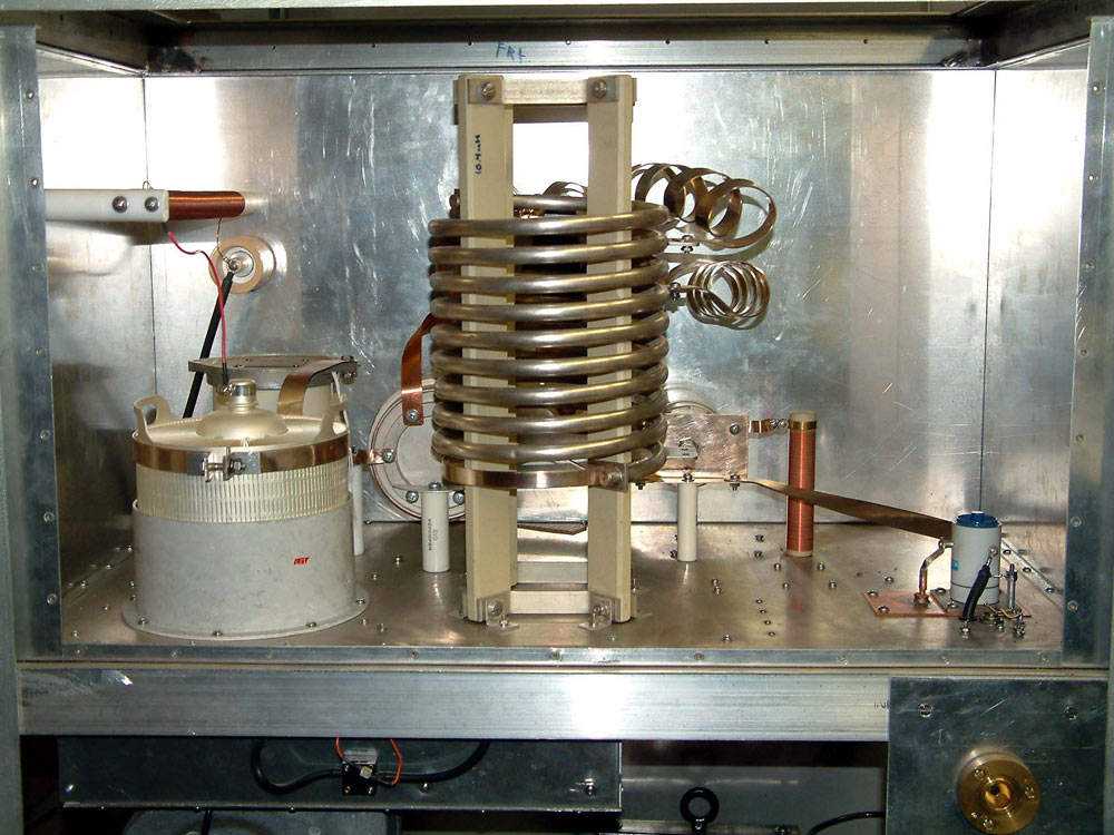
Anode to plate-tuning capacitor lead must be short, low inductance, and the chassis-to- socket path short and low inductance.
Components around the tube are the minimum safe distance to prevent arcing. This, along with wide smooth leads, keeps path inductance down.
The return from the vacuum plate tuning cap to the socket is through the wide subpanel. This subpanel is bent into a U shape, forming the side walls of the RF enclosure. Basically the entire RF deck is a cavity or fully enclosed box with removable back and top.
Screws are 3-inch spacing where only shielding HF signals, and less than 1.5 inches where VHF integrity is critical or ground current high.
One area with high ground currents is under the plate tuning vacuum capacitor.
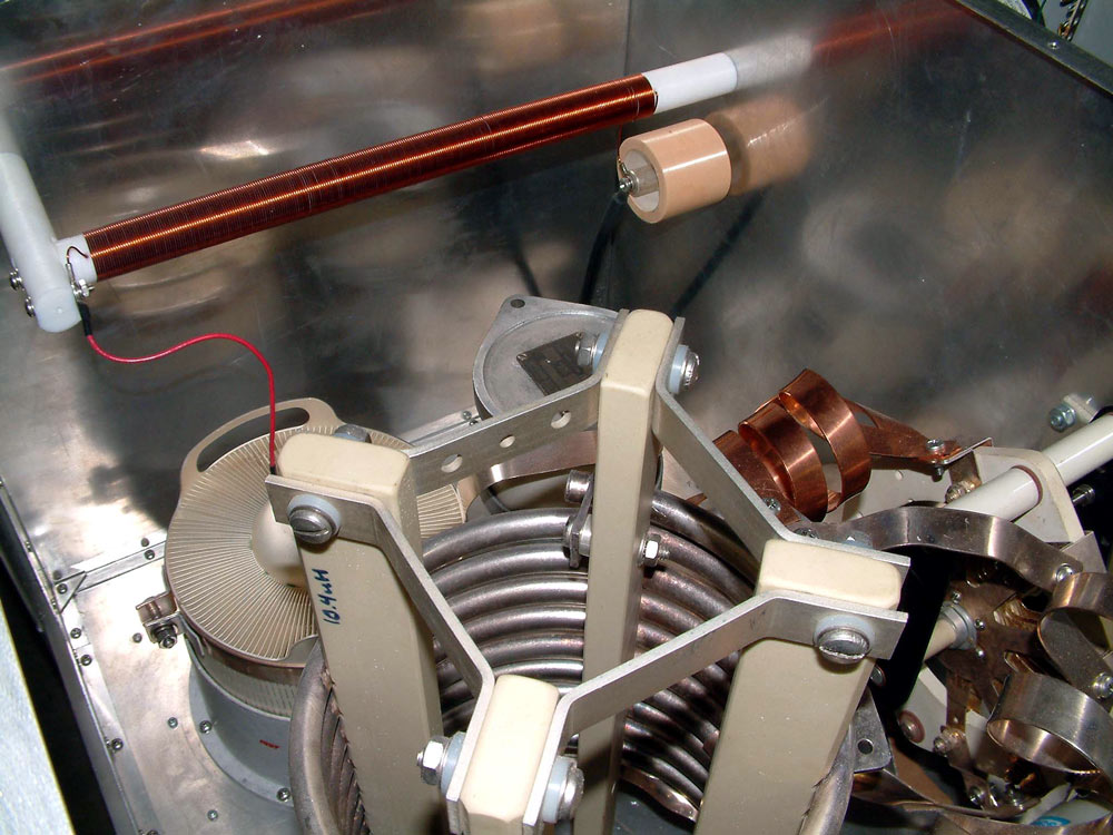
Note the plate choke is well-spaced from any metal, and is very slender and long. This is to improve voltage breakdown.
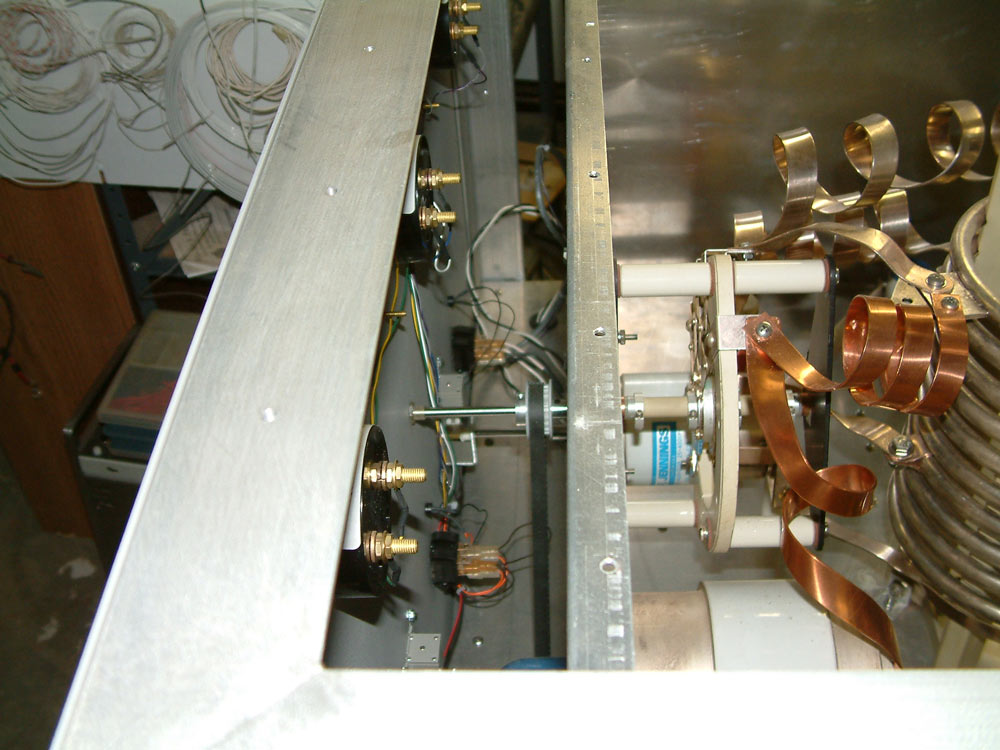
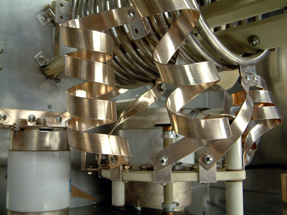
Tuned input is driven by a belt drive. Note the switch shaft does not extend into the switch, with bushings to ground the metal switch shaft. This photo is prior to final silver plating of tank leads.
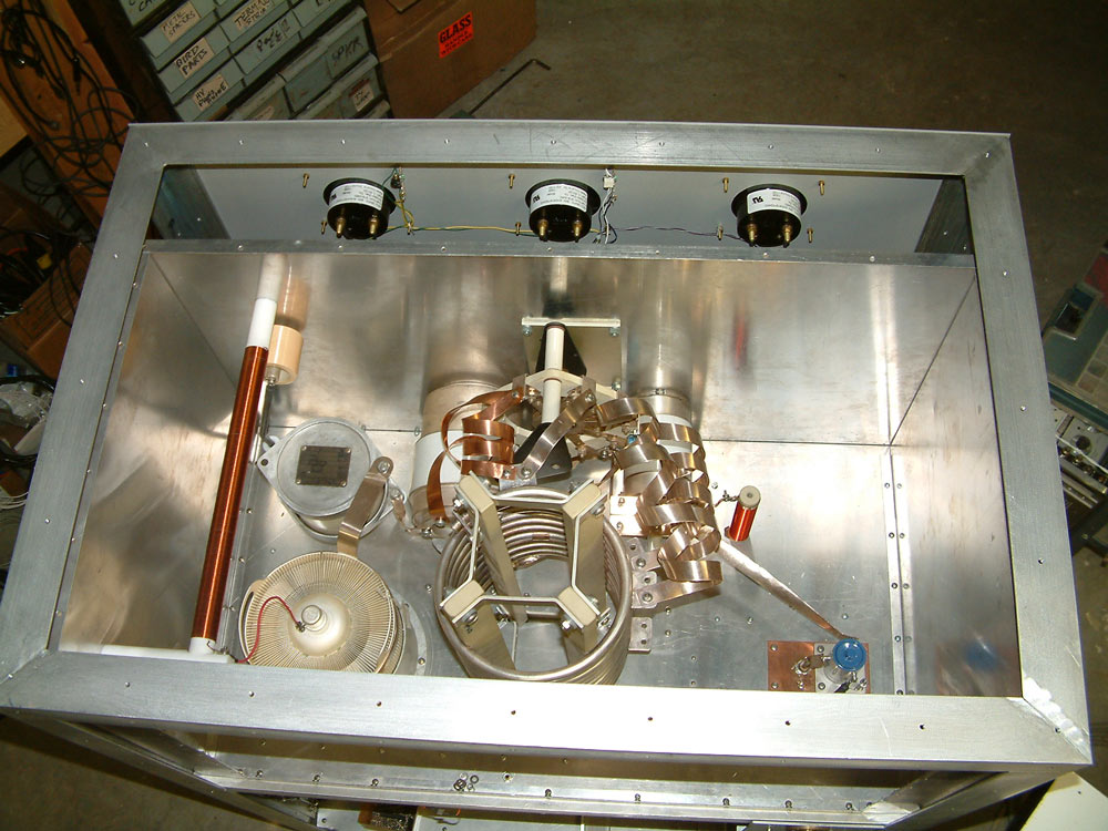
Tank frequency range is 3-22 MHz.
PA tube is a 3CX15,000A7 Eimac.
The output relay is a 30 ampere Jennings vacuum relay.
Teflon 1/2 inch semi-rigid cable goes down through the chassis to the 7/8th EIA flange antenna connector. A copper plate grounds the shield, preserving the RF integrity of the PA enclosure.
The black cable to the rear is the bypass cable.
7/8th EIA flange connector for output.
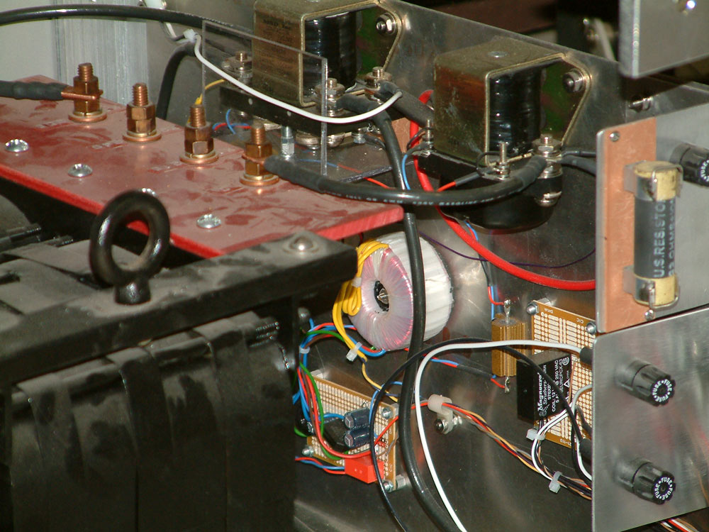
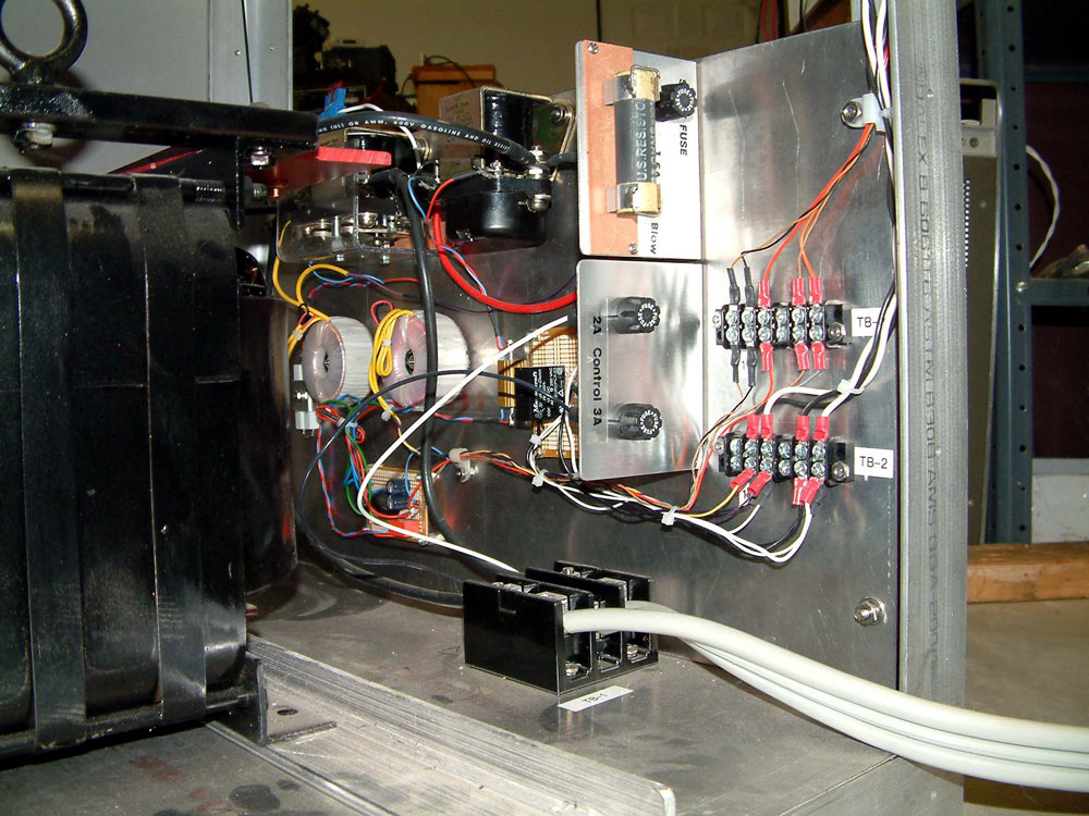
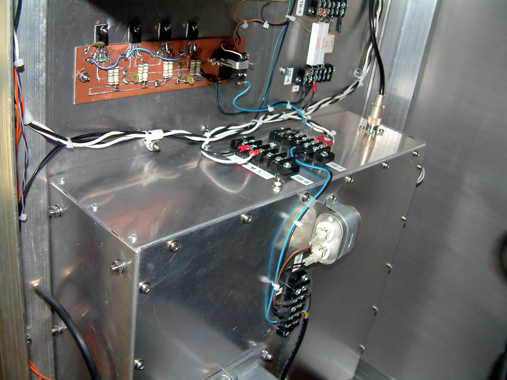
The air pressure switch is just below the tube with orange wires. This switch much close to activate the filaments, HV, and antenna relays. The main power switch turns on the blower, and blower pressure turns on LV control circuits. On power down, a thermal switch prevents disabling airflow when tube seals are above 100 degrees C.
Tank system.
Bottom of RF section. This RF tight box encloses the input tuning networks (which are far bigger than most amateur 1500 watt tank circuits) and filament supply and choke.
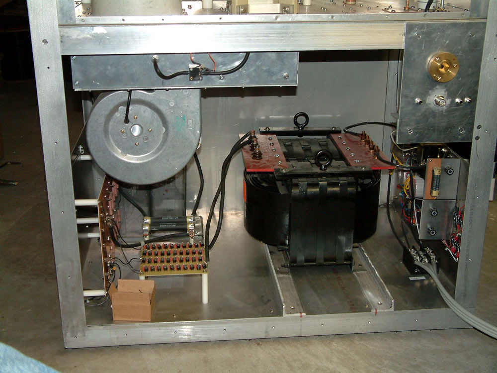
This is a temporary test transformer and rectifier.
Actual running supply is three-phase.
The low profile cabinet has wheels recessed below the bottom plate. The frame bottom is 1/4 inch aluminum plate welded to the 2 inch angle.
Input relay is a Jennings RJ1A.