Many antennas claimed to be bi-squares are not bi-squares. The assumption is if a "loop" is two wavelengths around the perimeter, no matter how constructed or shaped, it is a bi-square. The next guess or claim is usually, since the antenna was called a bisquare, it must have a certain gain. Usually the gain is claimed to be around 4 dBd. Unfortunately, a real optimized full-size bi-square only has about 2 dBd gain!
One might wonder why it is necessary to "pick on" certain designs. The answer is simple. By looking at common mistakes, we can learn very useful things that prevent us from making mistakes.
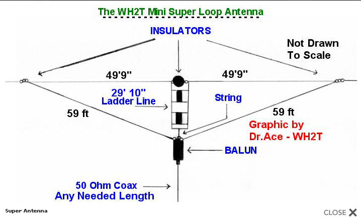
Here is an example of an antenna claimed to act as a bi-square, that really doesn't act like one. It is called a multi-band super mini loop antenna. (I will interject notes to call attention to certain errors.) The antenna is explained in the following:
| Antenna covers all bands 80-10 meters + 30, 17, 12
meter WARC Bands Any
antenna will cover all bands with a tuner. The question always is, "How
does is work?" An optimized shape real
Bi-Square antenna has 2 dBd gain The loop is an inverted vertical triangle with the base along the top and what would be the apex hanging down. Or it could be erected horizontally if needed. If that is done, it will beam straight up The feed point at the bottom uses a 3:1 or 4:1 balun and is then fed with any needed length of 50 ohm coax. Feed impedance models to be about 70 ohms. Obviously a 3:1 or 4:1 balun is incorrect The top center is broken with an insulator and has a
29 feet 10 inch length of 450 ohm ladder line connected across the
insulator. 450 ohm ladder line has an
impedance around 400 ohms or less Ladder line in stub or
transmission line mode cannot be treated as antenna length. Ladder line
is a stub, and must be treated as a stub. Not as physical antenna length That is true on 40, but on 80
meters it adds roughly about 400-ohms reactance because it is a 1/8th
wave shorted stub. We will see the problems this causes with SWR
A full wave loop, compressed in dimensions has much less than 1 dBd gain. That is hardly high performance, and the stub destroys harmonic resonances that are normally useful in loops On 40m it is a 2 wave length open loop or Bi-Square. The stub in the top leg of the antenna opens the loop when operating on 40m and selected other bands.This improves the antennas radiation pattern. Its gain is around 4dB, but it will seem a lot higher due to its excellent, low angle, radiation pattern. Untrue. Read what a bi-square
really is
Bi-square Link Laying the antenna horizontal will make it beam straight up. The saving grace is it is not that directional |
The diagram or pictorial is on Internet sites as follows:
Here is a model antenna:
This antenna roughly conforms to the dimensions and construction above, except length is adjusted for 40 meter resonance.
The stub destroys harmonic resonances normally present in loop antennas. In this case, when lowest 40 meter SWR is on 7.150 MHz, the 80-meter resonance is on 4.25 MHz. This is because the stub is in the circuit as a reactance on 80-meters.
When the shorted stub is resonant on 7.15 MHz, the antenna will ALWAYS have near-zero current at the middle of the top:
This happens because the stub is nearly an open circuit on 40 meters.
Having a current null at the top actually prevents the antenna from acting like a bi-square. The is because the center of wire 1 and wire 2 invert phase, so wires 1 and 2 "fight" themselves. This antenna is a bi-square bent into a shape that makes it stop working as a bi-square!!
To even remotely act like a bi-square, the antenna would have to bend near the current minimum in wires 1 and 2.
It was a very bad assumption to guess that the antenna would be a bi-square, and a very large exaggeration to claim it had 4 dBd gain. A real bi-square only has about 2 dBd gain, and this is not even close to a bi-square.
Gain on 7.15 MHz with the antenna 92-feet high at the very top wire.
Gain is 8.36 dBi, which is exactly the same a dipole at that approximate height! Gain is, as we might expect, zero dBd. It acts like a dipole on 40 meters.
80-meter gain:
80-meter gain is 5.62 dBi, this is about -3dBd. It has slightly negative gain compared to a dipole on 80 meters. (A dipole at optimum height is 8-8.5 dBi.)