|
Kenwood TL922 Amplifier
[ Home ] [ Up ] |
As with any old gear and our modern Internet, there are many needless (and sometimes detrimental) mods
published
for the Kenwood TL922 and TL922A amplifier.
I
don't believe any of this is malicious or intentional, it is just a byproduct of
bad information, experimental guesswork, and a desire for one simple answer to a variety of causes and
cures. Well intentioned Hams think they have found a
universal cure, even when the modification is detrimental to how the
system works and contrary to good engineering practices, because a
small sample of one or two units, often improperly tested, appears to function
OK.
The following event sequence is often used to "proove" a mod works:
- some old component that lasted many years fails
- the failed component is replaced
- a
special modification is installed
- the amplifier works again
That's not much of a surprise if we think about it. When a bad component or components,
in use for ten or twenty years or more before failure, are replaced..... quite naturally the
system
works again! Then, when the system works, the needless change immediately gets credit
for improving things.
One single source has diligently worked to convince amateurs that nearly
every arc, spark, pop, bang, component, or tube failure is a parasitic. This
source, of course, is the only source for the "true" cure. Send him money, and
every cause of past and future component failure is magically cured. Never mind that Eimac
engineers, and virtually everyone else experienced in RF engineering or power
grid tubes, finds fault with most everything he claims. Of course the natural
defense is there is an "industry wide conspiracy" to discredit him, and to
sell customers bad systems. Everyone likes
a good conspiracy theory, the Discovery Channel and other networks capture the
imaginations of viewers by presenting "evidence" of ancient aliens, big foot, and
an
occasional appearance of Elvis. If a larger cross section of viewers were
amateurs, no doubt they would have an "Ancient Parasitic" show, tying Egyptians
and pyramids to optimum shapes of nichrome parasitic suppressors.
Reviving a Modified Kenwood TL-922 Amplifier
A radio friend spent a great deal of money and time having his Kenwood TL922
amp modified. Despite a great deal of work, his amplifier never worked correctly for
any length of time.
This amplifier had the full treatment, including nichrome hairpins, but they had to
be removed because of "parasitics" or instability. I have no idea if the amp was
initially stable or not, but my best guess is his amplifier originally never had a parasitic.
Most likely, as with nearly all other amplifiers, it simply
had some bad 30-year-old parts. The only arc I witnessed in this TL-922 linear
was from a bandswitch wire routed too close to another wire.
This amplifier arrived with well-cooked RF Parts 3-500Z's. The tubes were
about 2 years old, and
were very low on emission despite all the filament voltage, nichrome, and inrush
modifications.
"Tom, After spending $500 for this amp 2 years ago and another $400
for repairs to getting it back on the air that’s $900 and now
another $400 for all the mods done to it that places it at $1300."
This TL-922 Kenwood was a victim of
very strange, but expensive, pathological science and engineering.
While parasitics certainly can occur, they are grossly
exaggerated in an effort to sell magical suppression kits. Stability
can be tested and confirmed by following procedures at this link
TESTING STABILITY.
There is no reason to guess!
An explanation of causes and cures for instability is at the
above
page and links from the page VHF
Stability
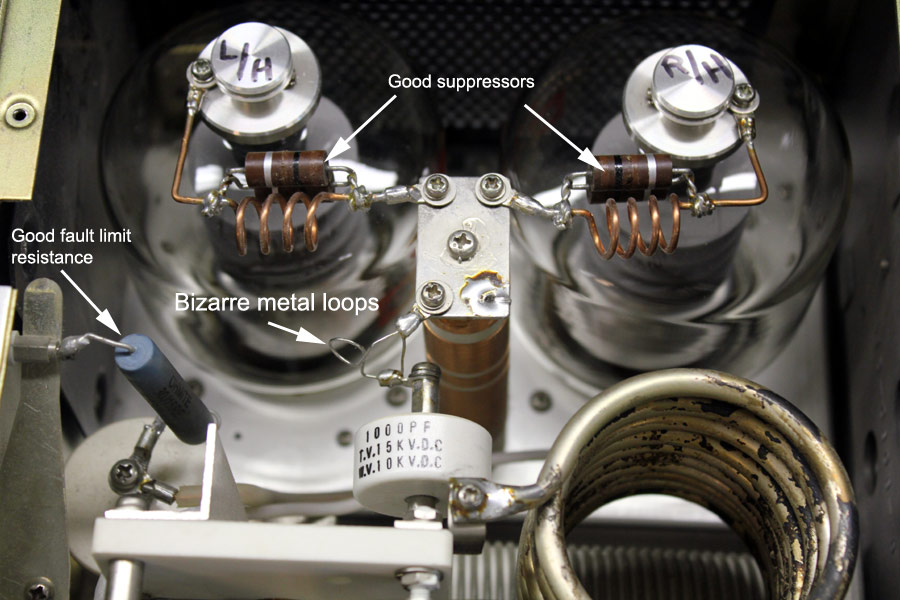
As received, this amplifier had reasonable looking suppressors,
with the exception of suppressor lead lengths being too long. At least it did not arrive
with the hairpin suppressors installed!
There is no reason to be "neat" in a tank circuit or RF system,
and angle wires at 90 degree bends. Squared corners and right angle
wiring, unless carefully planned, is almost always detrimental to
circuit performance. If you read the linked page on VHF parasitic
stability, you will understand why anode-to-chassis and
anode-to-grid paths must be short.
The parasitic suppressor, to be most effective, must have significant
impedance compared to the path from anode (inside the tube) to the chassis and
back to the grid (RF signal common ground point).
When we use long thin circuitous wiring in the anode system, we make a
parasitic suppressor of a given VHF loss resistance much less effective.
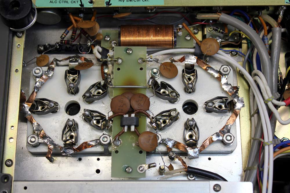
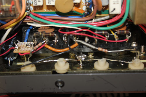
This TL922 amplifier had a some good rupgrades, but also had some bad
changes.
The 15 ohm HV fault limiting resistor at the middle-top is a good thing, even if not the best
style resistor. A better style would be a 175P pulse rated resistor.
The anode path was a problem, though. Not only was path length needlessly long from the modifications, a small
resistance element was added.
This was truly bizarre, RF-wise, because fairly high HF circulating currents
flow though this path on upper HF. It reduces upper HF tank unloaded Q
(that should be high for maximum efficiency), while reducing effectiveness of
the anode-to-plate choke VHF suppressors.
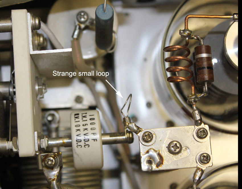
Not only that, it was a short straight wire shunting a tiny loop. There isn't
any logical RF rational for an odd wiring system like that.
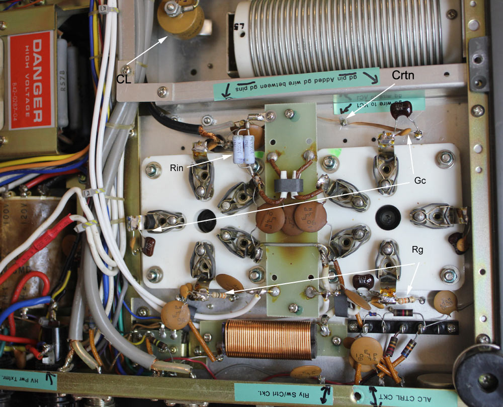
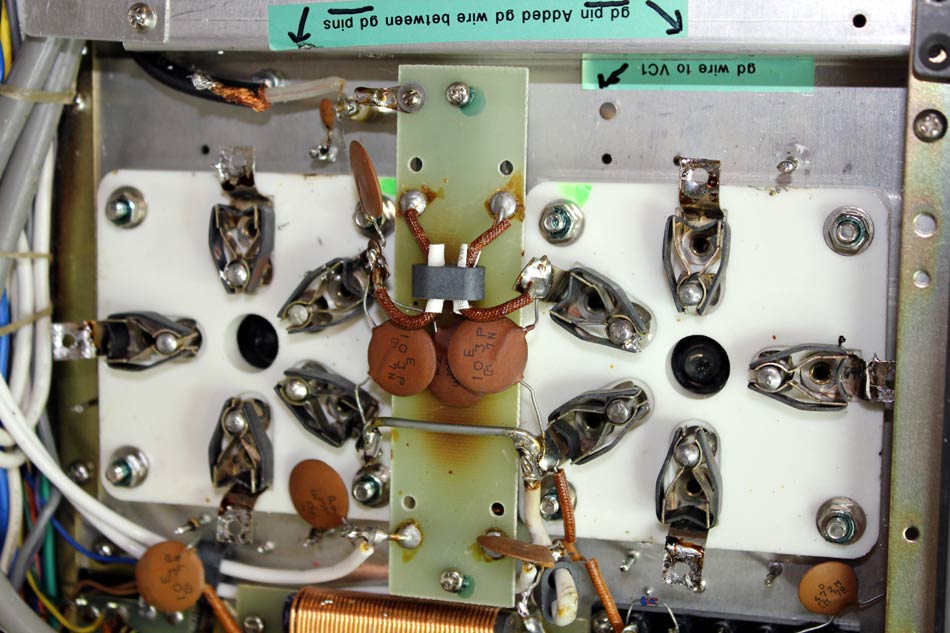
The TL922 had the wrong type of capacitors at CL. These caps need to be
temperature-stable high-current capacitors.
Rin was a parallel resistor combination. While it adds negative feedback, it
did not add enough negative feedback to be worthwhile, and ran quite hot.
The grids had different capacitor values Gc with long leads added, along with
very small resistors Rg. These parts serve no benefit at all, and only cause
problems.
The strangest thing of all was a copper strip Crtn connected between tube grid
pins that went up to the
rotor of the plate tuning capacitor. This wire has no useful function at HF or VHF! At
HF and lower, the shunting impedance of the plate capacitor and the grid
bypasses pretty much remove all current through the long thing white wire, and
at VHF the thin wire's length adds significant series impedance, while the
shunting impedances at each end bypass currents.
I don't know if this was from Kenwood, or if someone else cooked it up as a
modification, but the long thin wire from plate tuning capacitor to grid pins
serves no useful purpose.
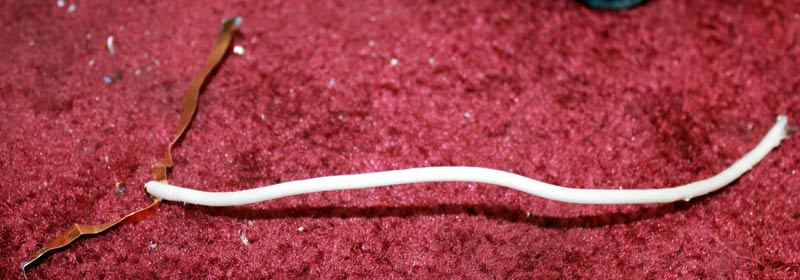
I de-wormed the TL922 by pulling this very odd hunk of wire out. Whoever
thought installing it was a good idea probably did not think through the system
or measure anything.
My guess is someone thought it would ground the plate variable back to the
grids for stability.
Into the trash it went!
I removed all the unnecessary parts from the grid and filament pins.
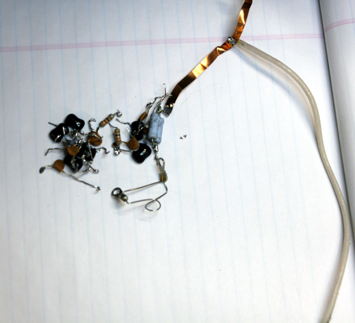
This is the pile of useless bottom parts, plus a thin magical parallel wire
nichrome combo from the tank system.
Grounded grid amplifiers, for a number of reasons including driver radio
safety, stability, and purity of emissions, should have the grid grounded. See
these links:
bottom of VHF Stability page
Super Cathode Drive section
811H 572
mods
No good ever comes from floating grids when they can be grounded, and I
stopped this practice in all amplifiers. I even removed it where I used it
in the past!
I added lugs and used some existing chassis pins. The grids now have wide
short multiple chassis connections.
One Internet mod says to ground only one TL922 amplifier grid pin. Do not follow
that advice!
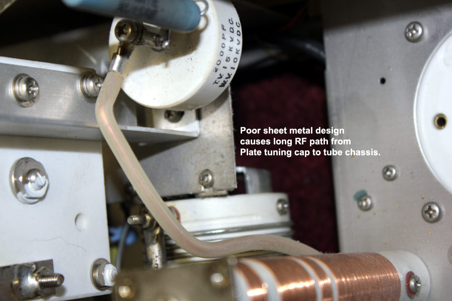
I'm sure this is a Kenwood TL922 design factory design flaw. The air variable
not only has a single very long ground connection path, there is a very long
path from that chassis section to the tube chassis. If a single screw in the
right place comes loose, the Plate capacitor will not be grounded!
The single small screw under the white doorknob capacitor is the sole ground
connection point for the air variable capacitor! The variable capacitor does not
even have a front bracket grounding wiper or chassis connection. It is not a
good design for VHF bypassing.
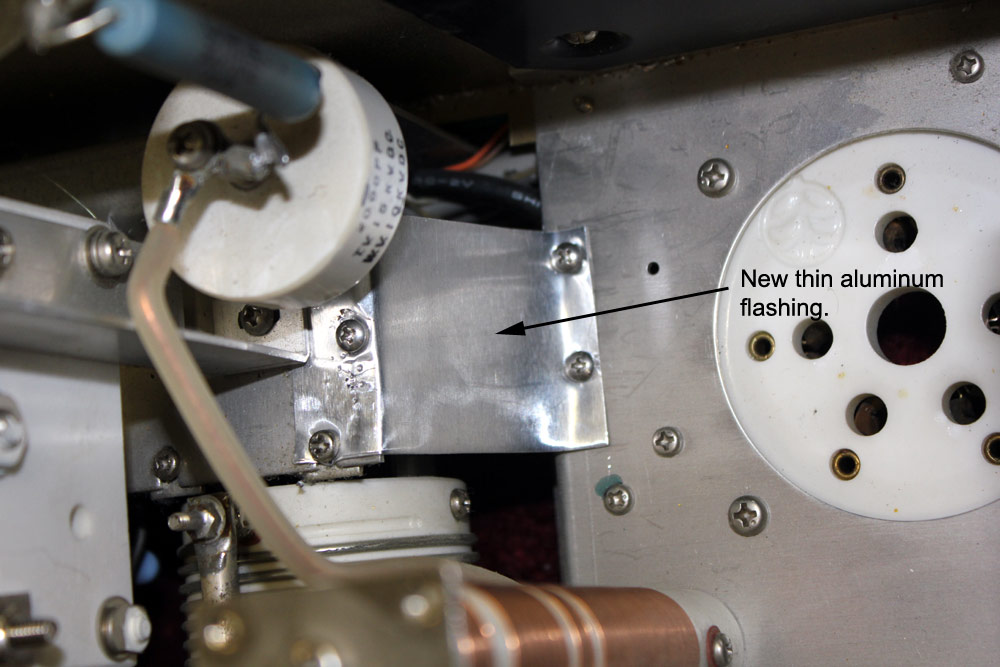
I added a direct connection between the tube chassis and the ground point for
the Plate Tune variable.
This largely corrects the TL922's terrible RF sheet metal design.
This type of capacitor is unsuited for high RF currents, and is unstable with
temperature changes.
RF current rating and temperature coefficient is critical in tank tuning
components.
Prepare by insulating and spacing the 160 padding capacitor lead, and adding
a ground lug if you use leaded parts.
The original parts were probably good, but the person who upgraded this amp
used small disc caps that burned up from RF current.
The owner then found larger caps, but they were poor RF capacitors.
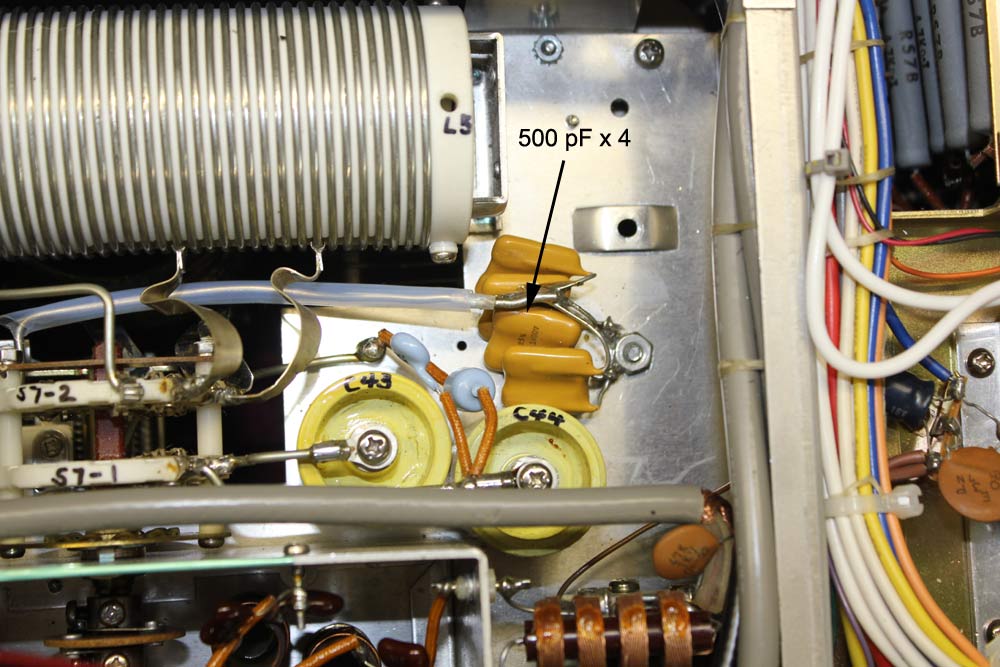
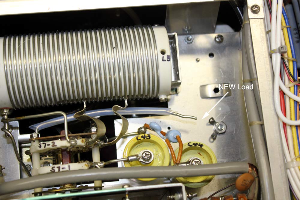
I initially used 4 x 500pF high current snubber mica capacitors in the 160
loading padder capacitors. They are temperature
stable and suitable for RF applications.
That was OK with the soft tubes, but with fresh tubes it was bit too much
capacitance. I found 2000pF was slightly too much capacitance, so I reduced it
to just a pair of 500 pF capacitors.
I settled on 1000 pF total with fresh tubes.
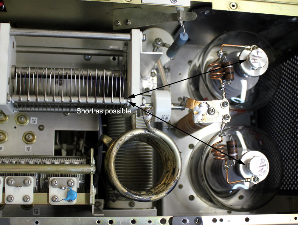
The path from anode to tank capacitor (and eventually to ground and back to the
grid) to ground should always be as short as possible.
Other than the suppressor coil itself, we always want this path to be the lowest
possible impedance at VHF. This not only improves stability, it also improves
efficiency and harmonic suppression.
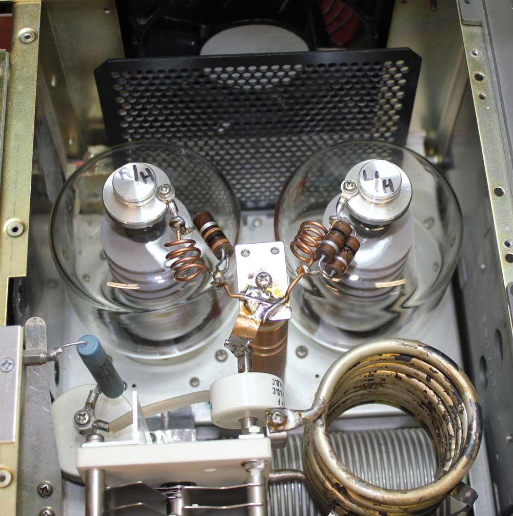
While not the neatest looking suppressor in the world, the suppressors installed
functioned perfectly.
I removed considerable lead length from the suppressor system.
I silver soldered to the existing bracket.
The only thing I really didn't like about the suppressor was the resistor
attachment method and the type of wire. It was a very hard bare copper.
The strap silver soldered to the doorknob blocking capacitor is soft copper
strip.
This amp had a step start system using a relay and 20 ohm resistor. It does not
make much difference at all in filament inrush. I measured inrush both with and
without, and other than a dt<0.1 second delay before the filament current peak,
everything was the same. It will probably help power switch life, but doesn't do
anything for actual inrush.
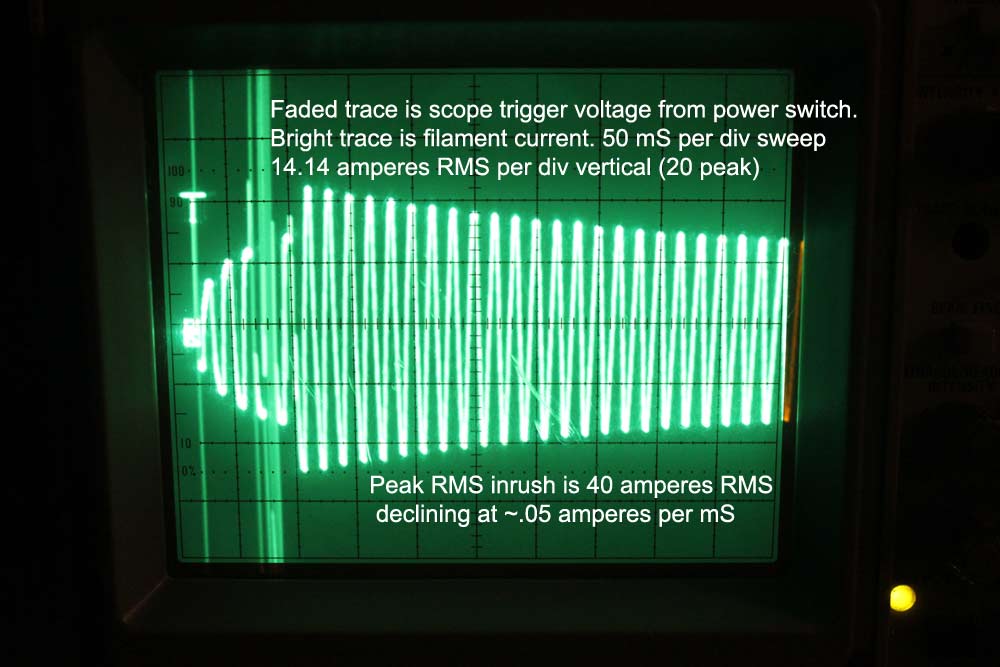
The tall traces are from switch and relay contact sparking. The spikes get in
through the trigger circuit, and are actually not present on the filament line.
The peak RMS filament current measured 43 amperes without the step start, and 40
amperes with the step-start system. The delay time is so short it is hardly
worthwhile for anything except extending power switch life.
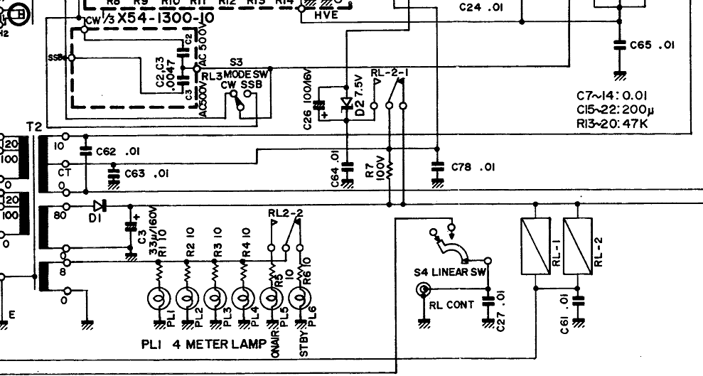
LED's for Meters
This amplifier had LED's in the meter lights. There was a small circuit board
added to power a step-start and new meter LED's.
This new dc supply board was sourced from the 8 VAC line feeding the old
incandescent meter lamps (very bottom 8 winding).
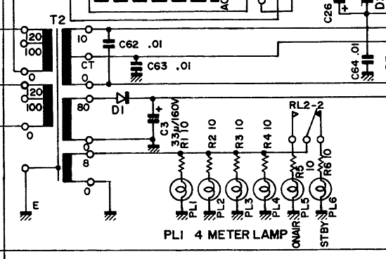
I was told the LED's had short life. This was because a small DC half-wave
supply with only 220 µF of capacitance was
used to power the LED's. This made a great deal of AC ripple, and to obtain good
brightness 100 ohm resistors were used. This made peak current around 65 mA,
with an average current of 40 mA. This slowly damaged the LED's.
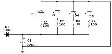
The replacement LED's were www.superbrightleds.com 5mm White LED p/n RL5-W15120
They have an average current rating of 30 mA.
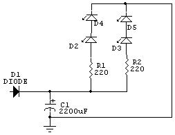
I replaced the original 220 µF with a
2200 µF. I put the LED's in series at each
meter, and used a 220 ohm 1/2 watt resistor on each supply line. This made
measured LED current 23 mA of nearly pure dc. Be sure you check LED current with
a DVM in series with the LED's. Adjust the current for less than rated LED
current!! In this amplifier, 220 ohms worked fine with two LED's in
series.
Meter Protection
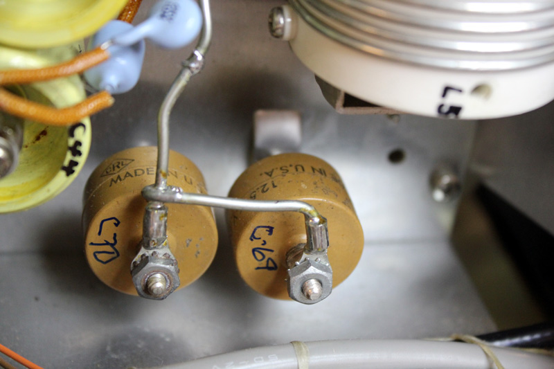
I added a negative rail clamping diode for meter and zener protection. I put a
1N5408 in parallel with a .1 µF 50 volt capacitor
across C65.
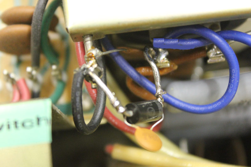
The negative supply rail clamp that protects the TL922 meters and other parts
connects across C65, from the bottom filter C15 capacitor negative terminal to
the chassis ground pin.
Cathode (band) end of the 1N5408 diode goes to the filter capacitor. Anode goes
to ground pin.
An explanation of why this works is
at this link.
RL-2-1also needs changed. Remove the wire from the normally closed contact. This
mod was already done in this amplifier. (The NC terminal of RL-2-1 was empty as
it arrived, so I did not have to make the change.) Removing the connection to
the NC terminal of RL-2-1 prevents damage to transformer T2's 80-volt
winding if a tube shorts from grid-to-filament.