 Figure
1
Figure
1
An engine outputs the same weight of fuel and air as exhaust that flows into the engine. The exhaust mass is simply the sum of fuel and air masses entering the engine. The power is created by thermal expansion of the intake mixture. While the mixture has constant mass or weight, the mixture has more pressure for any given volume when heated. The exhaust gas is far hotter than the intake mixture, so it occupies more volume at any given pressure. Of course as the exhaust cools the mass flowing occupies less volume, with more mass fitting in a smaller volume of space. The relationship between volume and heat, where heat increases volume, makes our systems work.
Energy driving the turbo is taken from the mass flowing through the turbine, the bulk from pressure delta across the turbine with a little from heat delta from inlet to outlet. It is not "free power", because the turbine back up the exhaust. The cylinders have to pump into that pressure.
As racers, we do all we can to increase the volume
of air and fuel running though our engines along with having maximum thermal difference between
unburned mixture flowing in and the burned mixture in the cylinder. We want to get as much cold
mixture as we can packed into the cylinders, ignite it at the correct time, and
get the hot exhaust out of the cylinder, making the cylinder ready for another fresh
cool charge. The more air and fuel we push through the system without damaging
anything, the happier we are.
Turbo systems increase power by packing more (hopefully cool) air and fuel into the cylinder. The turbo is a unique closed loop system. The more mass forced into the engine, the more mass exiting. Since that mass spins the turbine driving the compressor pressurizing the inlet, power rap[idly increases from the closed loop of intake mass being forced in and exhaust mass out powering the turbine. Wastegates are a critical part of controlling power created by a turbo. The wastegate controls turbine pressure, which controls compressor speed. This controls boost, and boost directly controls power.
Power added by boost directly relates to the pressure ratio increase to the base naturally aspirated power, less system power loss to run the turbine and compressor and any change in air temperature from compressing the air. The turbo produces a uniquely smooth power, with some pressure and exhaust remaining all though the four cycles. By controlling boost pressure, turbo cars easily and smoothly control power. The easy power management along with the smooth predictable burn is what sets turbo cars apart from other systems, with EFI turbo systems at the top of the turbo pack. The bulk of power management is centered around proper selection of the turbo, along with a good control system with one or more wastegates.
The turbine spins from exhaust mass moving through the turbine. The faster mass flows through the turbine, the faster the turbine spins. The more flow mass pushing against the blades, the more torque the shaft has. Of course blade size, shape, and pitch comes into play but that is set by the particular turbo.
The exhaust mass flow is exactly equal to the mass of air and fuel pushing into the engine. For a given thermal efficiency, a certain horsepower on a given fuel will always flow the same mass into the engine. The system at a given horsepower will flow exactly the same exhaust mass out for a given fuel and thermal efficiency, it does not matter what size the engine is!
If we are going to control turbo boost to some stable level below maximum, the wastegate must divert enough exhaust mass to slow the turbine and compressor to the proper speed. Obviously this is a mass flow ratio concern, not a power limit. As a matter of fact the more power we want to make the less flow the gate needs. The gate flow is opposite the power needed, with the highest gate flow needed at the lowest desired high RPM power level. Conversely, increasing power requires more exhaust through the turbine, and that means the system needs less gate flow. This is especially true at lower RPM or below the engine horsepower peak, where the engine flow volume from pumping is reduced.
The system needs the highest gate flow when commanding lowest target boost at
or around the engine's peak horsepower point. This is why so many systems have
"boost creep", where boost climbs higher and higher with increased engine RPM
and load. Boost "creeps up" because the wastegate cannot flow enough exhaust
mass to pull back exhaust mass going through the turbine enough to get the
system into equilibrium. At some high airflow mass the exhaust mass can't get
through the turbine, and a larger exhaust mass percentage diverts through the
gate. Eventually the system gets back into equilibrium at some higher than
desired boost level.
Boost creep is normally a flow ratio
problem at lower boost levels. The gate can't divert enough exhaust mass to slow
the turbine, the compressor spins too fast for the target boost.
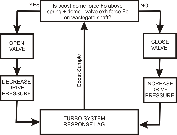
The waste gate system is based on a closed feedback loop. Figure 1 below. The loop is:
Figure
1
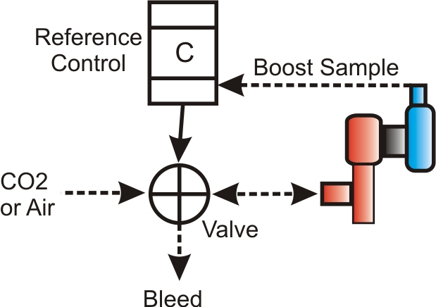
The most reliable and stable dome pressure control system applies external pressure to increase boost above some base pressure set by the spring.
 Figure
2
Figure
2
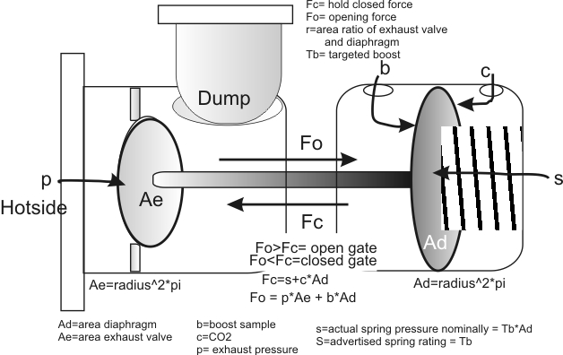
A typical wastegate
is shown in figure 3 below.
A boost pressure sample
signal is applied to b. Any boost pressure creates a force on
the diaphragm area Ad. The force is boost*Ad. Let's assume
boost is 10 pounds (psig) and with a 3" diameter diaphragm Ad
is 7 square inches. The net opening force Fo
is 10*7 = 70 lbs. The spring or other pressure source on the dome tries to hold
the wastegate closed. These two forces fight each other.
If the pressure Fc of spring S is less than 70
lbs., Fo will push the gate open until Fc and
Fo become equal, with force Fo opening Ae and reducing turbine drive
which ultimately
reduces boost.
As in any feedback system, control error heavily depends on feedback loop gain. The wastegate has an internal pneumatic pressure amplifier created by the ratio of dome diaphragm area to the exhaust control valve area. The dome diaphragm area to gate valve area ratio is often overlooked, but gate exhaust valve to dome diaphragm area ratios are critical to stable smooth gate operation.
 Figure
3
Figure
3
The ratio of diaphragm Ad to valve Ae is one of the most important and most overlooked parameters in wastegate design. The larger Ad (diaphragm area) is compared to Ae (exhaust valve area), the more consistent and stable the wastegate becomes.
Assuming negligible hotside pressure, S (spring pressure) in pounds, for a given boost opening pressure in PSI boost (pounds per square inch boost) is directly related to area Ad in square inches. The formula is S = Ad*PSI. If the diaphragm area is 3 square inches and we want 10 psi, spring pressure becomes 30 pounds! If we installed a spring that was 10 pounds of force the gate would crack open at 10/3=3.33 psi boost.
A large dome diaphragm area means the wastegate has a great deal of pressure actuating the valve. Large diaphragm area Ad means better seal of the valve and more positive valve action when the valve opens. This means a narrower and more reliable control window.
There is a second very important wastegate parameter, the ratio of dome diaphragm Ad to exhaust valve area Ae. A larger ratio of Ad to Ae means the valve opening point is less influenced by hotside pressure changes. As pressure p on Ae is increased, the valve tries to open and leak. This happens because the hotside pressure creates and opening force on the wastegate shaft. This force subtracts from the closing force.
The ratio of Ad to Ae creates a pneumatic pressure amplifier, much like the master cylinder area to wheel cylinder area does in a hydraulic braking system. It is, in effect, a pneumatic lever that increases control force of the larger size. A larger Ad to Ae ratio means higher pneumatic gain, requiring less CO2 pressure and spring pressure to hold the gate closed against exhaust. This effect is not proportional to the sizes, the effect is proportional to the square of the size change! If we double the physical size across the dome diaphragm, we have four times better control!
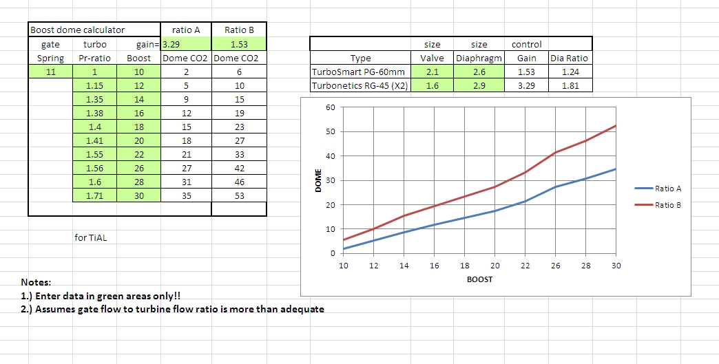
Figure 4 below is a spreadsheet I use to calculate boost. Figure 4 uses data taken from my engine with a Turbosmart PowerGate 60 and a Turbonetics RG-45 . Look carefully at the superior gain of the RG-45 and how that affects dome pressure. The steeper curve of the PG-60 is solely because of the poor diaphragm to valve area ratio.
Not only does the PG60 require more dome pressure to command more boost, it has a much wider valve hysteresis range in static testing, which means boost becomes less stable and predictable. The PG 60 is more difficult to spool, because exhaust pulses tend to knock the valve open more. When it does spool, the boost is less stable than the RG-45.
 Figure
4
Figure
4
The top right of figure 4 shows diameter ratio and the resulting pneumatic gain of two different wastegates I have tried. The Turbosmart Powergate 60 has an effective dome diaphragm diameter to exhaust valve diameter ratio of about 1.24:1. This gives a pneumatic control gain of 1.24^2 or 1.53. The Turbonetics RG-45 wastegate has an area ratio of 1.81:1, giving 1.81^2= 3.29 control gain. The Turbonetics RG-45 has about twice the pneumatic control gain.
The graph below the gain calculation table shows dome pressure required for a given boost. To obtain 30 psi boost at high RPM and engine loads, the low-gain Turbosmart gate requires over 53 psi of dome CO2 pressure, while the Turbonetics only requires 35 psi dome pressure. The lower gain gate requires almost twice the CO2 pressure at high boost.
A higher pneumatic gain wastegate is also much more boost control stable. With higher pneumatic gain, boost control error is smaller. The exhaust valve position control is less precise and increasingly influenced by exhaust pressure with reduced pneumatic gain. The Turbonetics gate typically has a boost sample pressure delta, from valve fully closed to valve fully open of about 3 psi. The lower gain Turbosmart shows a boost sample delta of about 6 psi. This means the higher gain Turbonetics gate tries to keep valve open within a 3 psi boost window, while the lower gain gate tries to hold boost within a 6 psi range. My estimated reliable engine limit is about 33-34 psi, so I can stay at 30 psi target with the RG-45 and be assured I stay within a certain overshoot. To be safe with the lower gain PG-60, I have to stay at 26 psi or less target boost or use a fast boost safety system to dump CO2 and revert to spring control.
If I did not use CO2 and used some simple inexpensive pressure bleed system or compressor pressure, gate valve stability and predictability is even worse.