Also see:
AL811H Amplifier Myths, Notes, and Hints
811A tube HF standby instability
811A Tube History and Construction
Full line of parts, service, and repair by designer at CTR Engineering, Inc
Modification to AL811 (and other 572/811 amplifiers with standby stability issues)
Occasionally AL811amplifiers (three tube versions) have been reported to cause receiver noises, like a popping or broadband noise. In some amplifiers, like the FL2100Z, certain tubes draw too much standby current, and with removal of the input and output loads, this allows the amplifier to oscillate while on standby. In the AL811 series, certain tubes with sharp cutoff characteristics can create a noise. This noise might be faintly heard, as a muted buzzing or clicking noise, from the rear panel area of the amplifier . The noise changes, starting and stopping and changing rates, as BAND, PLATE, and LOAD settings are changed. This happens only on standby. If the amplifier includes gas protection tubes on the filaments, the gas tubes will fire on upper bands under certain settings of TUNE and LOAD.
While there are a variety of problems due to inconsistency in production of 811 and 572 tubes, this particular problem appears to be related to the cutoff characteristics of the 811A tubes. There are more details at this page 811A tubes . Tubes with sharper cutoff have the problem, while tubes with more remote cutoff do not.
Link to AL811 recommended field modification
Modification to AL811H
| Important note!
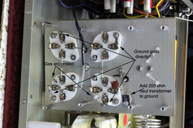
I suggest removing C32-C35 , removing R19 through R22, and directly grounding the grids with a short heavy lead in the AL811H. Also install two 150-volt to 170-volt gas voltage protectors, one from each filament line at any tube socket to ground at the socket. These components were initially used to equalize tube load sharing more, but because newer tubes tend to arc more (poor pumping and poorer materials/cleanliness/quality control at the tube manufacturers) it is safer and more reliable to eliminate these components. |
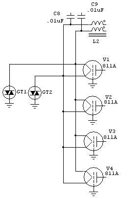
This is an important modification to the AL811H. This mod removes the grid resistors and bypass capacitors, and directly grounds the grids.
In addition two gas voltage clamps, GT1 and GT2, are added. These are 125-150 volt clamps. I have them available for $10 including shipping.
This mod prevents:
1.) relay damage
2.) exciter damage
3.) grid resistor failure
Since the AL811H amplifier was initially designed, vacuum tube construction has become less reliable. Tubes these days have much more tendency to arc from anode to grid.
This modification improves reliability of the amplifier by directly grounding grids. Amplifiers produced after early in year of 2011 have this modification. If your amplifier has resistors mounted on terminal strips near the tube, it could use this mod.
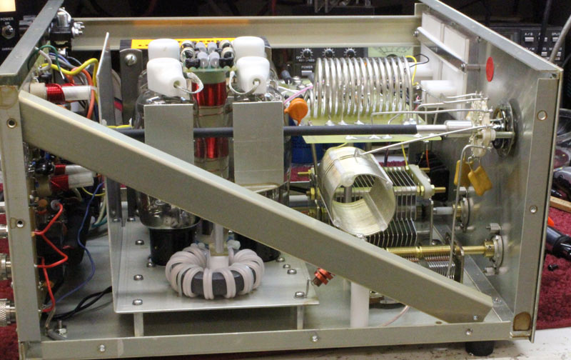
Remove side bars.
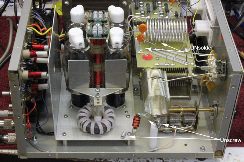
Unsolder orange blocking capacitors from #8 wire that goes to Plate tuning cap.
Remove screw that holds RF choke lug to LF tank coil. Be careful to not knick or cut the fine insulated wire in the choke winding!
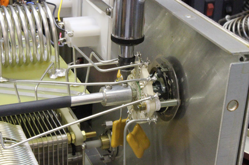
Loosen the FRONT setscrew only.
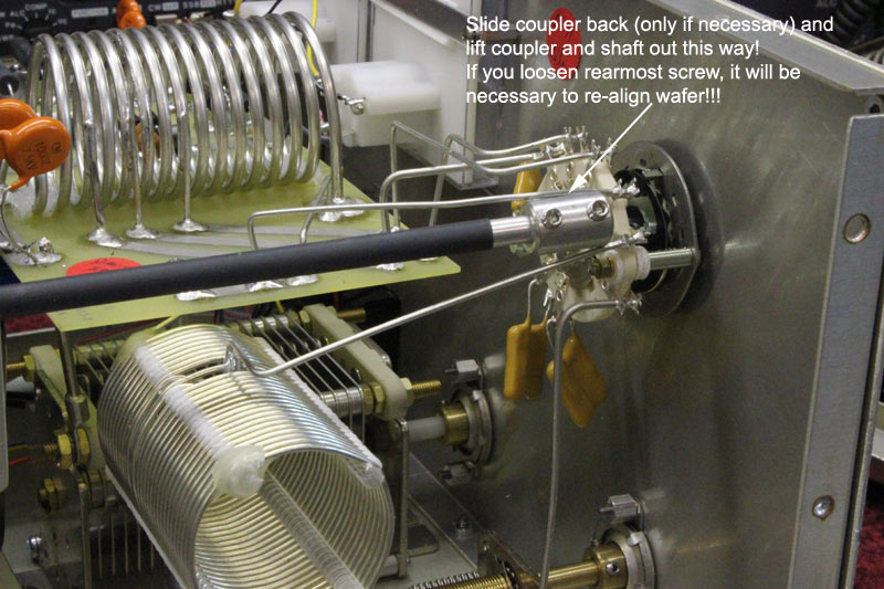
Slide the shaft coupler back off the switch.
If the switch is out of alignment, see this page
Slide the shaft forward to remove from the input circuit bandswitch. Be careful with this switch. It can be damaged and changing it is a real pain.
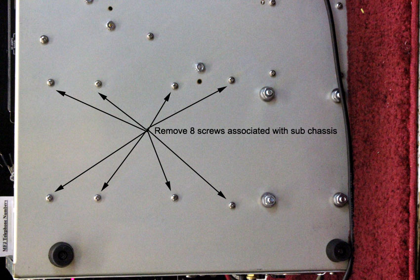
Remove the tube sub-chassis.
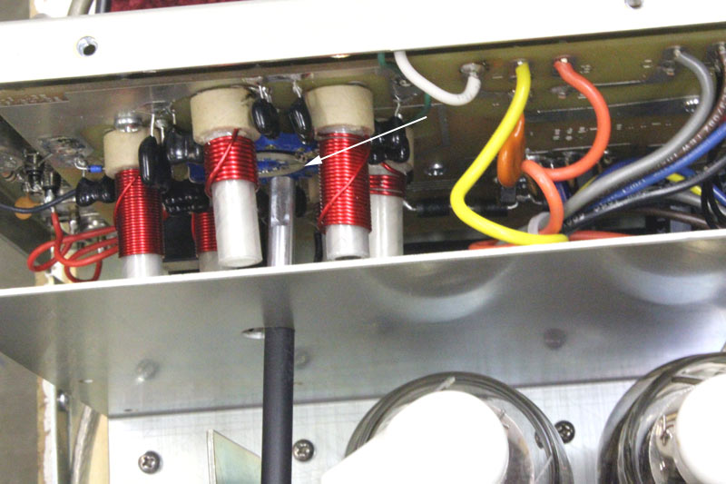
The 200-ohm non-inductive 25 watt resistor is fully across the neutralizing
transformer, from the .01 uF capacitor to ground. This resistor is less critical
in the AL811H. It slightly increases drive power requirements to more closely match
the AL811H to 100-watt radios. However, it also improves stability with some
Chinese tubes. I strongly suggest using it.
Warning!!
THIS
MODIFICATION IS MANDITORY IN THE AL811! In the AL811, there is no
neutralizing transformer. The .01uF disc capacitor must be added. It can connect
to any filament pin. It goes through the resistor to ground with short leads.
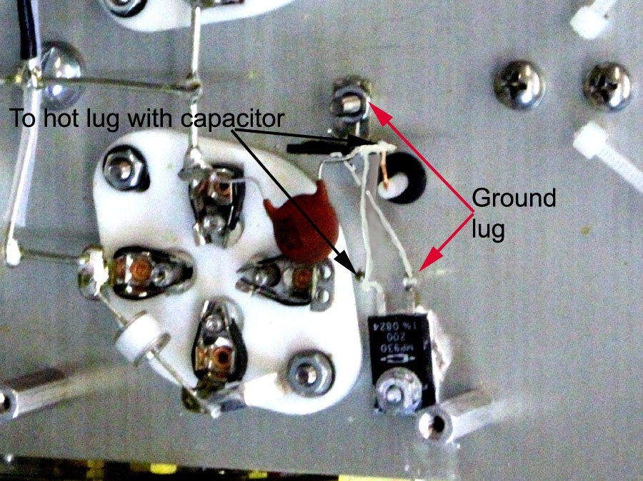
The 200 ohm resistor connects across the neutralization transformer winding feedpoint to ground in the AL811H.
In the AL811, the resistor connects from filament through a .01 uF 1kV to ground.