Under Construction this under construction
The Johnson 275 watt and Kilowatt Matchboxes are both unnecessarily exaggerated and unnecessarily maligned. They are not exceptional tuners. They are not poor designs. The primary drawbacks are the fixed coupling link, and the fact they are balanced VOLTAGE sources, not the generally more ideal current source.
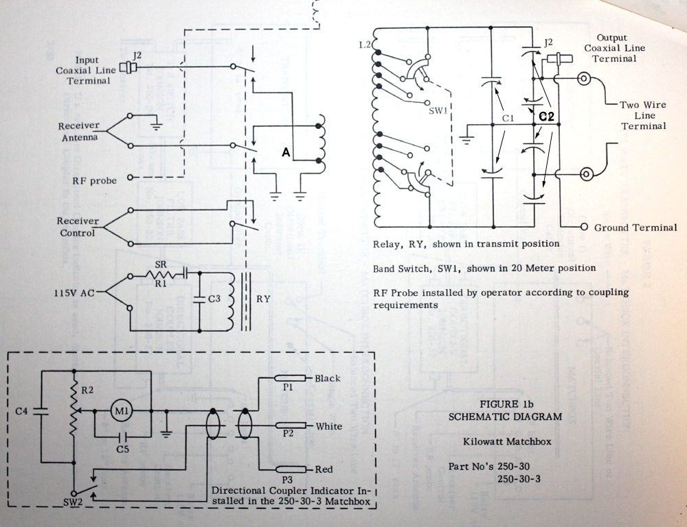
In the Johnson Matchbox, C1 is a standard dual-section TUNING capacitor. C1 has a common dual area rotor, and a split stator.
C2 is special and expensive. C2 is a dual-differential MATCHING capacitor with four capacitor sections. C2 has two insulated rotor areas in differential tied to the balanced outputs, two independent stators, and two commonly-connected stators.
C2 is overcomplicated, with unnecessary sections in C2. The unnecessary sections of C2 are the two sections connected to ground. The two unnecessary grounded sections neither benefit nor harm tuner performance significantly. The tuner works almost identically when grounded inner sections of MATCHING capacitor C2 are eliminated.
The fact Johnson included unnecessary grounded sections of C2 does not make it a bad tuner. The inclusion of unnecessary (basically harmless) sections only means Johnson wasted money and space inside the tuner by including the nearly-useless grounded C2 MATCHING capacitor sections.
In the 1980's, I designed an Ameritron ATR-10 antenna tuner (not related to any current Ameritron products). The ATR10 Ameritron was a companion to the AL84, and was designed as a companion bandpass 600-watt antenna tuner. The Ameritron ATR10 antenna tuner used a network functionally identical to the Johnson Matchbox series. The ATR-10 was a single-ended tuner with an output balun. The ATR-10 used a tapped inductor instead of a coupling link. The basic simplified ATR10 antenna tuner matching circuit is shown below:
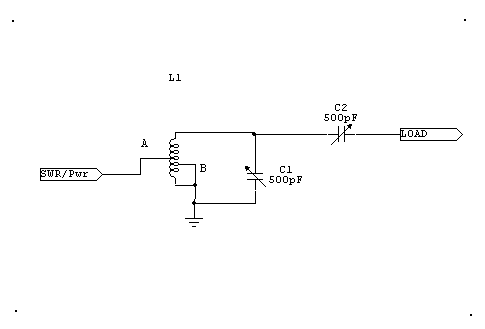
Tap A is from a standard rotary switch contact. This tap always leads tap B toward the hot end of the tank. The amount of lead controls tank Q. Tank Q determines matching range and power rating, just as changing turns controls Q and range in any link coupled tuner.
Tap B is the band selector tap. This switch is a progressively-shorting (pick-up-and-hold) contact. Tap B determines inductance, which in turn sets frequency range.
If we ignore the nearly useless grounded sections of C2 in the Johnson Matchbox, and understand a link is not much different electrically from the tap on the ATR10 Ameritron, we see the ATR10 and EFJ Matchbox are electrically identical in matching function.
I dispensed with the needless shunt capacitor on the output in my ATR10 design.
The Ameritron ATR10 and E.F. Johnson Matchbox tuners both use a combination series and parallel resonant output circuit. This circuit actually forms a T network. If we assume C2 is set to resonance and C1 has zero capacitance, we have a classic link coupled series tuned network with low output impedance. If C2 is set to a high capacitance value, and C1 is tuned to resonance, we have a classic parallel tuned network. In both cases the tap-point A distance above band-point B sets maximum impedance ratio, because the tap point determines maximum operating Q and available voltage at the common junction of L1 top, C1, and C2.
C1 primarily determines load resistance value, while C2 primarily compensates reactance. Ironically, Johnson calls C2 Match and C1 Tune! Lowest impedance is with C1 open and C2 tuned to correct resonance. Impedance increases as C1 is moved closed, with C2 progressively closed. Highest impedance is with C2 fully closed and C1 tuned to resonance.
If we are mindful of how the ATR10 works, we will also understand the more complex Johnson Matchbox. In the case of the Matchbox series, the number of turns on the LINK coil sets matching range and maximum power capability of the tuner.
The EF Johnson, unlike the ATR10, does not maintain the same primary-to-secondary ratio as bands are changed. The Johnson KW and 275 watt Matchbox tuners have widest matching range and highest Q, and lowest power rating, on lower bands. Conversely, the Johnson tuner has narrowest match range and lowest Q, and highest power rating, on upper bands. This is the result of using a fixed number of link turns, while varying L2 turns significantly.
My solution to this issue in the EFJ tuner is to make extra taps available as a transmit option, and slightly modify the tap positions. This provides external selection of Q and match range. To accomplish this, I installed an extra pair of connectors. Other options would be an additional internal switch, or the addition of a suitable series capacitor on the link.
This type of network, unless we can vary the link, has a limited matching range.
Actual dipole and tuner measurements link
Spacing inductors away from sheet metal.
A typical #14 or 16 gauge B&W Airdux or Miniductor coil might have a Q of 300 in open air, and that Q might drop to 260 or so with sheet metal near the axis.
Here are some actual measurements of a small 3" diameter air core coil. This
particular coil uses fairly thin wire and is not of optimum form factor, so basic open-air Q is
only around 160. The following measurements are with the coil axis spaced around
1/4-inch from a large flat metal sheet. This coil is from a MFJ 300 watt tuner.
Measurements are on 2 MHz. Measurements are made on an HP4191A impedance test
set (the industry standard for measuring or characterizing components):
Air for several inches around the coil = 160
Aluminum = 150
Copper = 152
steel = 142
stainless steel = 70
nichrome sheet= 62
We can see some materials greatly decrease Q, but most materials of reasonable or good conductivity have little overall effect on Q.
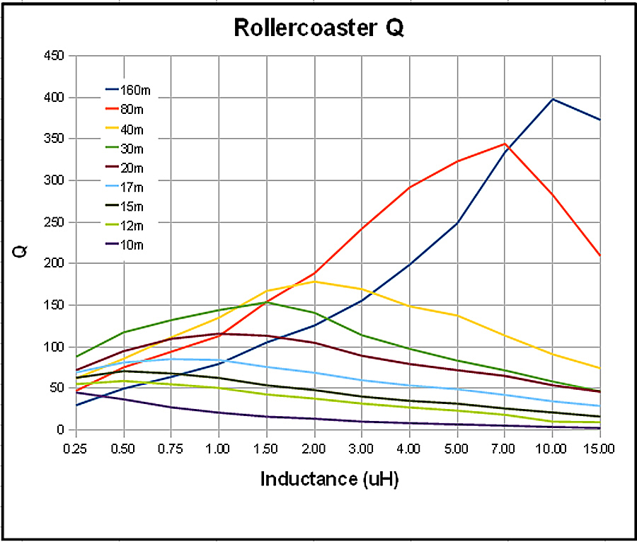
Roller Inductor Q
The following data was supplied by G3TXQ Steve. When I enter my data in a spread sheet, I will post it also. The trend of Steve's data agrees with my measurements, although there are differences in data because I measured different inductors. I measured less peak Q, but also significantly higher minimum Q in the inductors I tested. While the inductors I measured has less delta in Q, they also had a serious dip in Q up near 25-35 MHz when near half-inductance. This is because of series resonances.
Notice that shorted turns do NOT have the drastic effect sometimes predicted in amateur articles. For example, look at the 160 meter Q. It actually peaks with some turns shorted!
Do not worry about shorted turns reducing Q in a normal air-core inductor. There are cases where Q can be significantly reduced, but they are not common cases. In many cases shorting unused turns can increase Q. I will post measurements of shorted turns and Q as I measure new design projects.
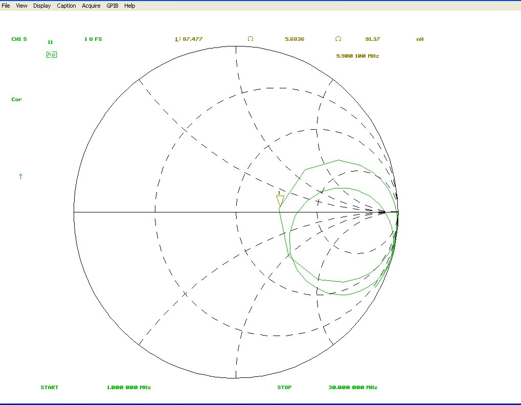
The sweep below, taken on an 8753C vector network analyzer, shows roller to chassis terminal impedance from a floating roller's frame. The cyclic impedance pattern below is indicative of series resonances, which also reduce roller Q. This would go away if the roller was "shorted" at multiple points in the unused areas of the roller, but such designs are difficult at best.
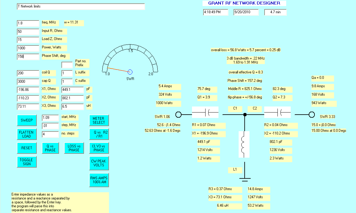
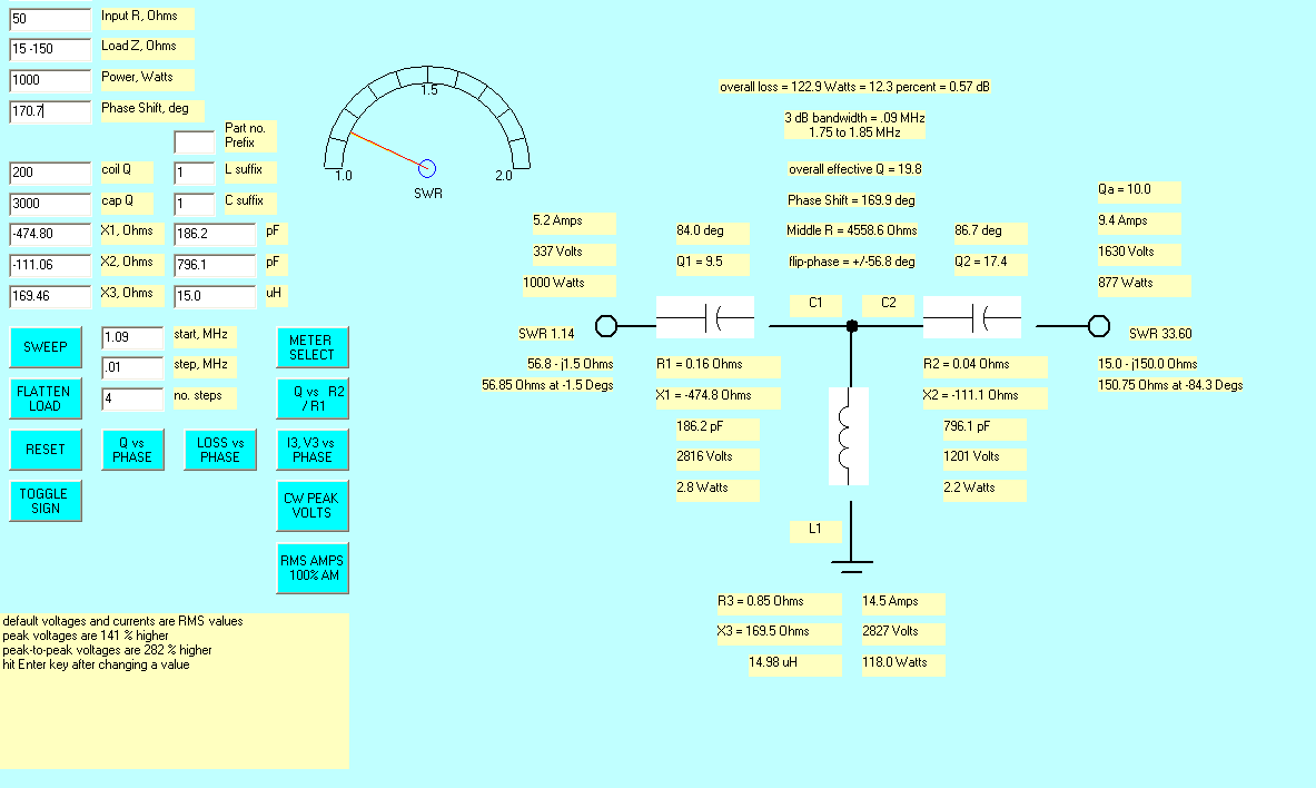
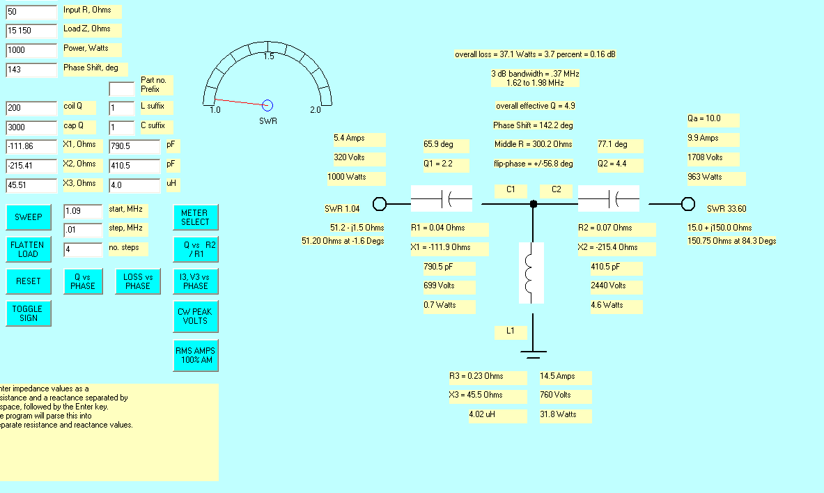
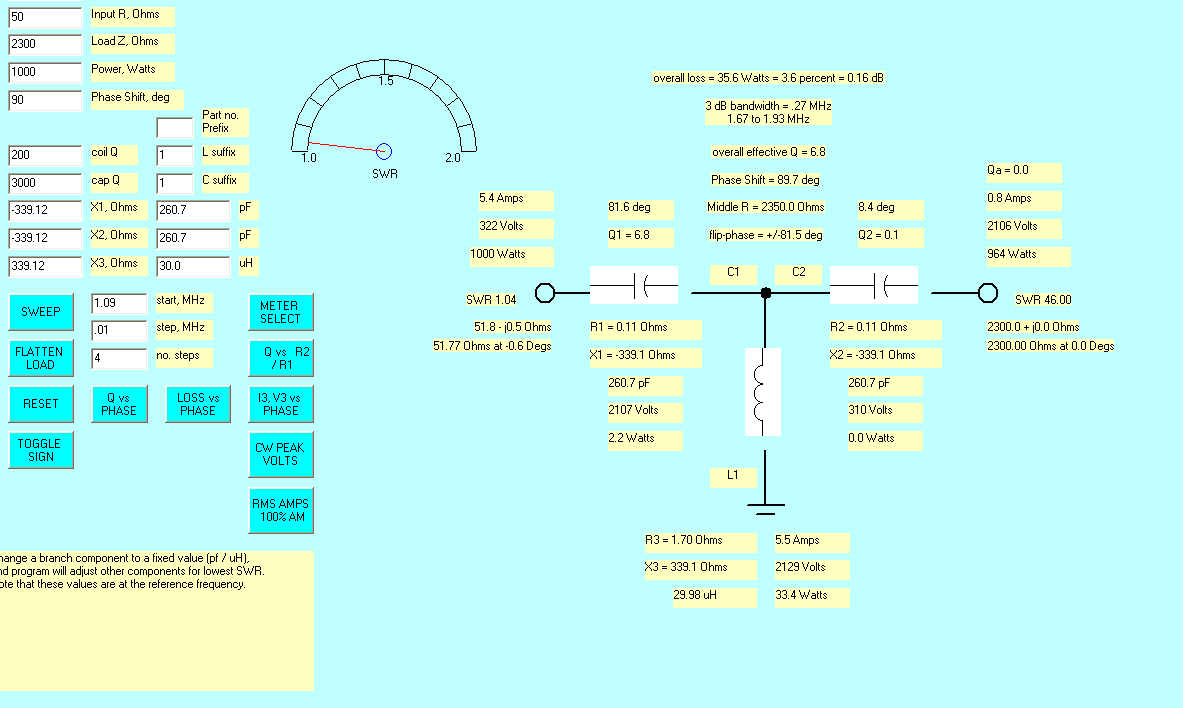
One endless argument is which network is better, a T-network or an L-network. This argument goes on continuously because each network has advantages and disadvantages, while in actual fact loss differences are really fairly small.
If we budget similar amounts of money, the L-network generally has a little less loss. The saving grace of the L-network is it just won't match a bad load impedance. The L-network "self-protects", and generally won't match loads that greatly increase network heating.
The T-network has much wider matching range! The T-network also requires less switching and fewer components.
L-Network = capacitance 15-2700 pF (Q=3000 overly optimistic at high capacitance), inductance .1 to 30 µH (Q=200). Note: I'm working to correct the Q's and make them more realistic.
T-Network = capacitance 10-800 pF (Q=3000), inductance 30 µH (Q=200).
The L-network's capacitor must vary from 15 pF all the way up to 2700 pF, and at one kilowatt the capacitor has to be over 2000 volts rating if the tuner is going to feed high impedance loads. This means we either use a large vacuum capacitor, or the design must switch various fixed capacitors in parallel with a lower-capacitance high-voltage variable capacitor.
The Q for the T-network is probably pretty close to normal values except for low inductance values.
The Q for the L-network is far too high for fixed capacitors (should be around 1000 or less), and too high for the inductor across the range (way too high at low inductance).
| Frequency | Load impedance | loss L | Loss T |
| 1.8 MHz | 15 -j150 | .38dB | .57 dB |
| 15 j0 | .03 dB | .25 dB | |
| 15 j150 | can't match above 15 +j22 | .16 dB | |
| 15 j22.9 | limit of L network | ||
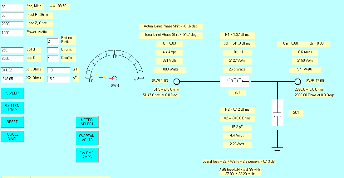
| 2380 j0 | .13 dB | .16 dB | |
| 4000 | can't match above 2380 j0 | .20 dB | |
| 30 MHz | 8 j0 | .04 dB | need to run |
| 15j0 | need to run | .04 dB | |
| 2380 | .13 dB | .16 dB | |
| 4000 | can't match | .2 dB |
Note, green lines are corrected Q=200 L network.
L-networks have a very wide range of impedances they just will not match, and they require extraordinarily high values of capacitance to do what they can do. To approach a T-network in matching range, they would require switching the network into four possible configurations plus the extraordinarily large values of capacitance. Because of these restrictions, L-networks have limited utility on a 1.8-30 MHz all purpose tuner. L-networks are great for matching known load impedances on a single band, but are cumbersome and expense to properly implement in a wide range general matching network application. If you are lucky with load impedances, you will swear by them. If you are not lucky, you will swear at them because they just won't match things a cheaper poorer quality T network will easily match.
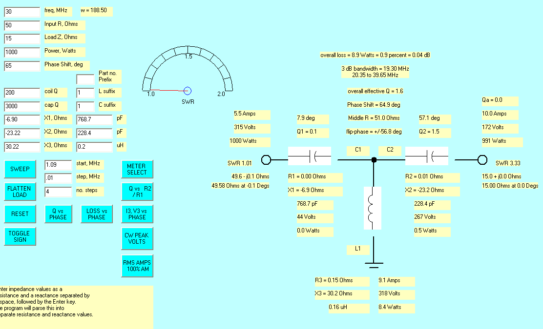
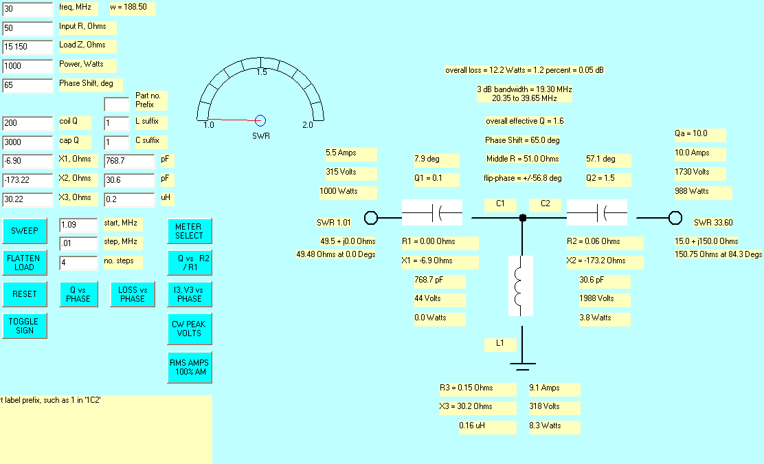
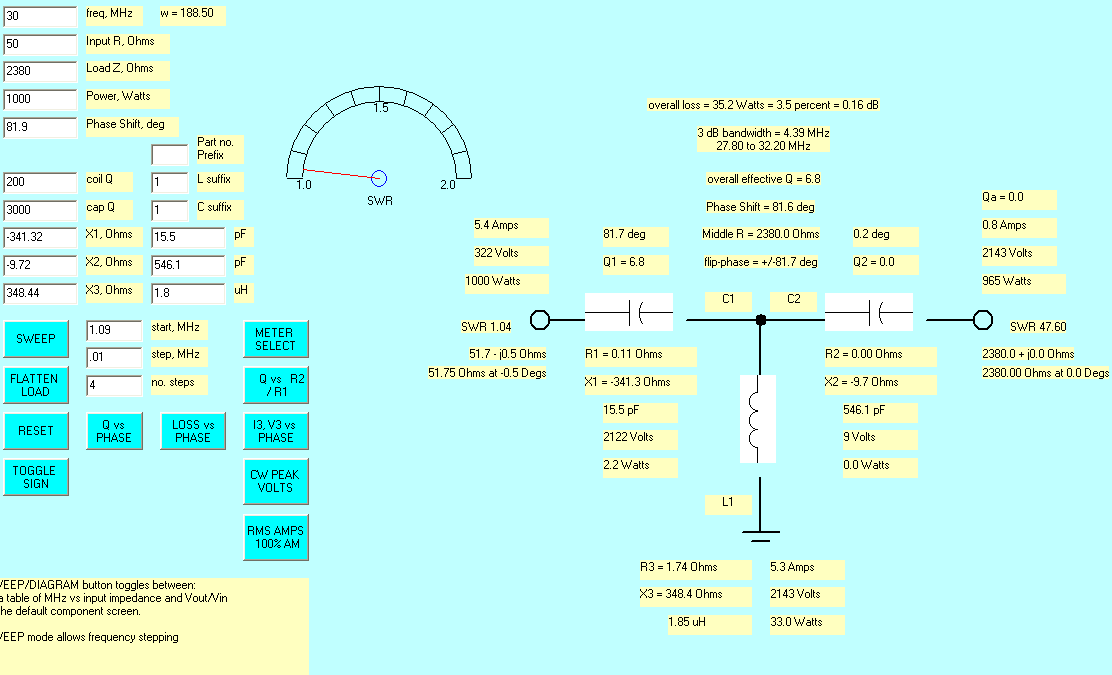
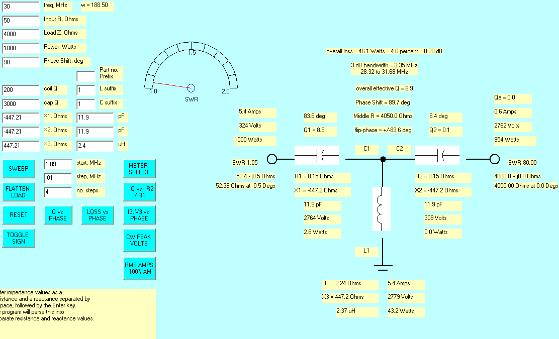
Loaded or operating Q is important in any impedance matching network. Loaded Q is the actual working Q, not the individual component "static" Q or "quality". For example if we have a capacitor with a Q of 3000 and a reactance of 3000 ohms, it has a series resistance of 1 ohm (or a shunt resistance of 9-megohms). This is quite possible in an air variable capacitor, but few small ceramic single layer capacitors produce such high Q's. If we shunt that capacitor across a load of 300 ohms, the loaded Q becomes just slightly less than 10.
Phase shift and network loaded or operating Q are closely related. The greater Q for a given impedance transformation ratio, the greater network phase shift becomes. The table below assumes a 1:1 impedance ratio. Q will be higher for larger impedance ratios.
A common rumor is there is only one optimum setting for
maximum efficiency in a T-network. Let's look at some numbers using realistic "amateur product"
Q values of 200 in the inductor and 3000 in the capacitors. This produces
numbers where a rule of thumb works. With 1000 watts in, the loss in watts is
approximately equal to phase shift up to 90 degrees!!! The loss table for 1000
watts applied, when matching 50-ohms to 50-ohms, would be:
| Phase shift | Q | Power loss out of 1000 Watts |
| 0 deg | 0 | 0 loss |
| 5 deg | 0.1 | .5 watts loss |
| 20 deg | 0.2 | 2 watts loss |
| 40 deg | 0.5 | 4 watts loss |
| 90 deg | 1.4 | 10.6 watts loss |
| 130 deg | 3 | 22 watts (only 0.1 dB loss) |
| 140 deg | 3.9 | 29 watts (-0.13 dB) |
| 150 deg | 5.3 | 38.3 watts (-0.17 dB) |
| 160 deg | 8.0 | 57 watts (-0.26 dB) |
| 170 deg | 16.2 | 109 watts (-0.5 dB) |
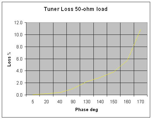
From 0 degrees to 130 degrees phase shift, a T-network with modest Q components has less than 0.1 dB loss!
The real problem with loss is power handling, not signal loss. We need to be very careful where a few watts of loss occurs, because even a few watts can heat something very small to a high temperature. We would like loss to be spread out over a wide area in physically large components so the heat "gets out". Most of the time it is, but unfortunately some of the time it is not. Careful tuning will minimize potential problems.
There is little change in efficiency or performance over a wide range of Q's. This is because loss is very low, so even doubling loss makes very little difference in power. Doubling loss will of course double heat, but the larger problem is the increase in capacitor voltages. Arcing can cause a tuner to fail even while loss in signal level is totally undetectable at the other end of a QSO. Arcing is a fast failure and very destructive, because it produces localized heating. Besides increasing voltages and heat, increasing Q also decreases bandwidth. This means a tuner requires more frequent retuning when operating frequency is changed within a band.
In order to minimize the need to retune and maximize the power rating of a tuner, it is necessary to tune or match with the minimum possible operating Q. In a T-network, we want minimum inductance and somewhere around the maximum possible capacitance that allows a good match. The quickest way to damage a switch or capacitor in a tuner is to adjust the tuner with too much inductance.
The worse advice, when tuning a T network tuner, is to start with the capacitor mid-way and adjust the inductor for maximum noise or minimum SWR. On lower bands the capacitors should be set to maximum capacitance as a starting point. Normally halfway open is a good place for the higher bands, typically 15 meters and higher in a 160-10 meter tuner.
160-80 meters=fully meshed
60-20 meters=3/4 meshed
20-10 meters=1/2 meshed
L-Network with maximum C of 2700 pF, and maximum L of 30 µH.

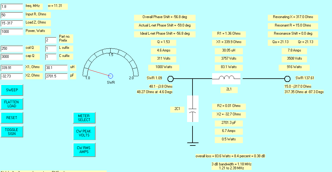
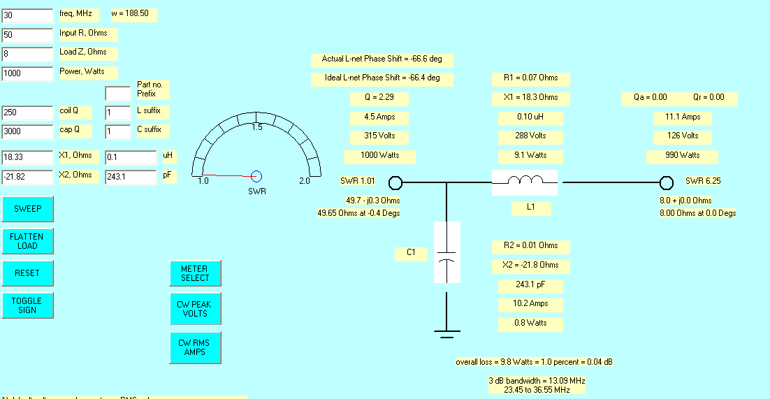
This is the lower impedance limit of an L network with 2700 pF of capacitance. It will not match any positive (inductive) reactance above 22.9 ohms on 1.8 MHz.
This narrow matching range, even with large values of components, is one drawback of an L network.
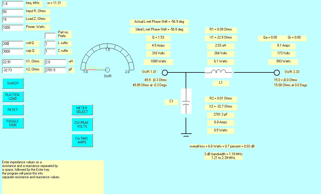
This is the maximum capacitive load that can be matched at 15 ohms resistive. At 15 -j317 the network is out of inductance.
The L network has poor matching range for low impedance loads, and requires a very large capacitor for 1.8 MHz.
Like the T network, loss is reduced with inductive loads.

The L network has a good reactance range if we lower the resistance down from maximum, but the capacitor and switch must be able to handle 2150 volts at 1000 watts.
Note we had to reverse the network.
The low Z limit on ten meters is set by the stray inductance.
Ten meters with high impedance limit.
The high Z limit on ten meters is set by stray capacitance.