Also see antenna tuners
I never really used link coupling very much. My very first transmitter, and all transmitters after that, used pi networks. A few years ago I acquired a transmitter using link coupling. I thought it would be fun to learn how and why a link system works like it does.
Owen Duffy, VK1OD, analyzes link coupling at this link. Owen's web page helped steer me in the correct direction, and I found the applicable information in the RCA Radiotron Handbook and Ryder's Third Edition of "Electronic Fundamentals and Applications" in section 6-7 "Inductively coupled circuits".
Someday when I have time, I will finish my project and measurements. I have a great deal of measurement data to put up here, and it reasonably well agrees with the analysis below.
Re-writing VK1OD's analysis a bit and expanding on it, we have the standard formula for mutual inductance as:
M = k * square root of (L1*L2) or as Owen says M = k(L1*L2)^1/2 since raising to the 1/2 power is the same as a square root
(you can find that formula here and in some textbooks)
L1 = La + Lc
L2 = Lb + Lc
Q ~ R1/XC1
XL1 ~ Xc1
Let's assume we can go as much as 50% on coupling coefficient and as little as 10%, and we have 4 µH for L1. At 7 MHz L1 is 175.93 ohms. That would be a 1.5 inch diameter 14 turn coil about 2 inches long. Let's make the link 3.5 turns 1.75 inches diameter and about 0.25 inches long. That's 1 µH for the link.
If we have 10% coupling k from L2 being moved away from L1, we would have M= .1* sqrt(4*1) and with all values in µH this makes M = 0.2 µH.
We have the following values:
La = 3.8 µH
Lb = .8 µH
Lc = .2 µH
Using any Smith Chart or equivalent program, we find the impedance presented at the tube with a 50 ohm load to be 2601 ohms.
Let's move the link in close until coupling k rises to .5
Now we have:
M = .5* sqrt(4*1) and so M = 1 µH
La = 3 µH
Lb = 0 µH
Lc = 1 µH
R1 = 1148 ohms with a 50 ohm load. This lower resistance increases anode current, perhaps as much as doubling anode current.
Checking the limit of the system of K=1 (perfect coupling) we have:
M = 1 * sqrt of (4*1) so M = 2
This means our circuit:
La = 2 µH, Lb = -1 µH, and Lc = 2 µH
this satisfies the requirement that Lb+Lc = 1 µH and that La+Lc = 4 µH
If we run this in a Smith Chart or do the math long hand, we find the 50-ohm load is transformed to 200 ohms. This is a 4:1 ratio. We can never have less than a 4:1 impedance ratio with a link inductance of 1 µH and a tank inductance of 4 µH. We start out with something over a 4:1 transformation ratio with the tightest possible coupling, and go up in ratio from that as we swing the link away from the tank coil.
It's very easy to see why swinging the link in changes anode current (increasing PA coupling or loading). In short the further out we swing the link, the lower anode current is at tank resonance because we increase the impedance seen by the anode. We lighten the load on the PA.
Series Capacitance in the Link
A second method I looked at was augmenting my swinging link with a series-connected variable capacitor.
The equivalent circuit would be the same as above, with an additional capacitor in series with the load.
At the top, original link. At the bottom, link with capacitor.
The system with C2 enters into a Smith Chart the same way, with the addition of that component.
Assuming a k of .5 and the original values of 4 µH and 1 µH for the link we have:
M = .5 * sqrt (1µH*4µH) so M = 2 µH
We have the following values to enter into the Smith Chart:
La=2µH Lb= -1µH Lc=2µH . We can now vary C2 and see how R1 varies with R2 fixed at 50 ohms.
| Freq 7 MHz | |
| C2 pF | R1 |
| 50 | 55000 |
| 100 | 13000 |
| 200 | 2900 |
| 300 | 1400 |
| 400 | 980 |
| 500 | 850 |
| 600 | 810 |
| 700 | 800 |
| 800 | 807 |
| 900 | 820 |
| 1000 | 835 |
| 1100 | 850 |
| 1200 | 865 |
Actual Circuit
data I already have put up someday soon I hope
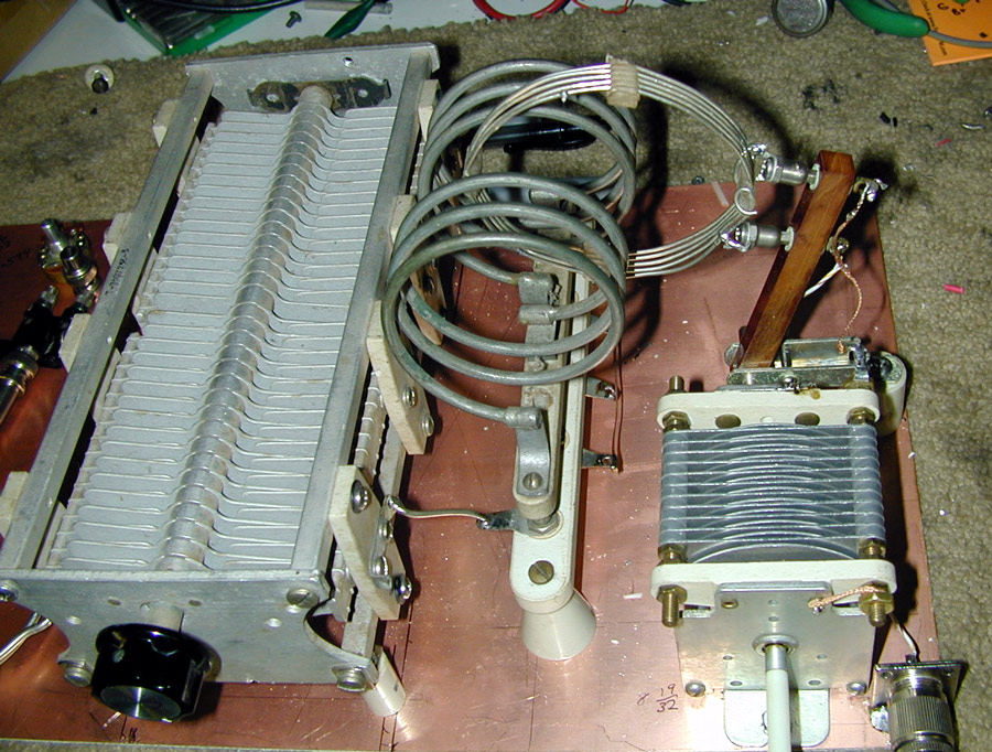
Playing with my 8005 rig, I wanted to learn how link coupling behaves. There is very little information on how link coupling actually works. I ran some tests using this test network:
C1 250 pF dual section
C2 220 pF variable
C3 various mica padding
L1 various plug-in tank coils
L2 link, two or five turns
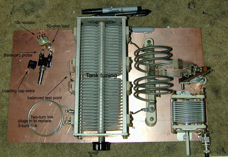
This test network is a swinging link coil with either five turns or two turns. It is series tuned with a 250 pF capacitor, and I have various micas or a short to connect across the variable capacitor.
I had a 10k variable resistor as a rough load.
An accurate 50-ohm load.
Extra capacitors for link tuning.
Probes.
Fixed resistors.
Various link coils.