Curtain Antennas
|
Curtain Antennas |
Lazy H Antenna, Bi-Square, Sterba Curtain, HR, HRS, and USIA Curtainand Bruce Array Antenna Arraysalso see Rhombic Antenna page
Three towers support two 2-bay wide 4-bay high 5 band curtains at Radio New Zealand International.
These two 300+ foot tall towers will support my new distributed feed curtain array for 80 and 40 meters. From all indications this will be the highest gain array ever installed and used exclusively for amateur radio service on 80 and 40 meters. Read how the curtain evolves in the article below.
Reference for gain, the DIPOLEIn order to understand gain, we have to understand the signal from a good basic antenna like the dipole. A dipole is the normal reference for comparing antennas. The dipole is also a basic building block of many antennas. Let's dispel a common gain misconception about dipoles and isotropic radiators. A dipole does NOT have 2.2dB gain over an isotropic radiator when the dipole is placed over earth. At optimum heights, a common 1/2 wave dipole actually has about 8.5 dB gain over an isotropic radiator! Always remember that when you see antenna models over earth that tell you an antenna's gain in dBi. If a model over earth shows a "gain" of about 8.5 dBi, the model effectively has the same gain as a dipole at optimum height over typical earth! We cannot add 2.15 dB to the isotropic gain to get the dBi gain unless ALL of the antennas are in free-space! The instant the earth is involved in a model or measurement the 2.15 dB rule flies out the window. The plots below are for a 145-foot high copper wire dipole modeled with high-accuracy ground over medium real earth on EZNEC:
You can see the gain is 8.5 dBi and it is just a simple dipole just over 1/2 wave high. Any antenna we model should be compared to a standard like a dipole over real earth (unless we intend to install the antenna in outer space)! What is a Curtain Antenna?Properly constructed curtain arrays or curtain antennas are a form of broadside radiators. Their name derives from the similarity to a wire "curtain", or a wide flat sheet hanging vertically. The curtain's flat wide form occurs because broadside radiators generally use elements aligned in a flat plane at right angles to maximum radiation. Properly designed curtains require a minimum number of elements to obtain optimum gain for a given physical area. Other antennas may be less complicated to build, but a properly designed curtain has the highest gain for a given volume of space of any large array. Rhombics are no match for curtains, and neither are Yagis, unless perhaps the curtain is a curtain of made of small Yagis! A few advantages of properly designed curtain arrays are:
Curtains can assume several common forms. These forms include vertically polarized arrays like the Bobtail, Bruce arrays, and H arrays. They also more commonly include horizontally polarized arrays like bedspring arrays, Sterba curtains, lazy-H antenna arrays, or distributed feed curtains like the USIA arrays or HRS arrays used for shortwave broadcast. Two common installers of large broadcast curtain arrays were TCI and Weldon and Carr. While E J Sterba (E. J. Sterba, "Theoretical and practical aspects of directional. transmitting systems," PROC. IRE, vol. 19,. pp. 1184-1215) pioneered some early closed-loop curtains, they were mostly single frequency designs. This article covers the design of several common curtain arrays. Lazy H AntennaThe Lazy H is probably the most elementary form of curtain antennas. The lazy-H usually consists of two horizontally polarized doublet or dipole elements, although with some loss in earth reflection gain it can be oriented vertically as an "H". Each lazy-H element has in-phase currents. The lazy H always has broadside gain from parallel in-phase elements. If elements are extended beyond 1/2 wavelength but less than 1.3 wavelengths, the lazy H can have collinear gain . There are several publications and Internet pages showing incorrect or substandard feed methods. This is the common transposed feed line arrangement. This substandard feed method is highly dependent on feed-system electrical length, needlessly sacrificing gain, and restricting bandwidth! This layout appears many places, including an often referenced internet article:
At least one article containing this drawing claims the elements are being fed out-of-phase. It further states the array will work multiple bands with the feed system shown on the left. The reasoning behind that statement is understandable. After all, the feed line is transposed. At a glance, we might assume the feed line transposition causes the elements to be out-of-phase, but that is not true. In reality, all broadside curtain arrays feed elements in-phase, never out-of-phase. In-phase elements radiate broadside to the element plane, or broadside to the plane of the "curtain" formed by the elements. If elements are fed out-of-phase, fields from each element combine out of phase to form a null. If broadside elements are fed out-of-phase with equal currents, a deep null forms broadside to the array. Most of the radiation would be at very high angles, or skewed toward the ends. Any curtain array must feed the elements in-phase, not out-of-phase. In the simple array pictured here, this is accomplished by having a feed line electrically 1/2 wave long and a 180 degree flip. A 180 degree feed line plus a 180 degree flip results in 360 degrees of shift, which is the same point on a circle as zero. The total phase shift is zero, the elements are in-phase.
There are three major problems in this first design example:
This antenna's pattern, with the bottom element 20-feet above ground, is shown in the following models:
Remember a dipole over earth at optimum height has about 8.5 dBi gain. To convert dBi to dBd we should subtract 8.5 dB from the dBi value given in the model. 11.92 dBi - 8.5 dB dipole over earth = 3.42 dBd. The above antenna has about 3.4 dBd gain on 28 MHz, which is slightly more gain than an Extended Double Zepp. Now let's see if the Lazy-H with transposed feed is really a multi-band curtain antenna. Looking at 21 MHz:
Because of feed phase errors, this feed system tries to force a high angle lobe. The transposed feed Lazy-H antenna produces less than one dBd gain on 21 MHz. On 21 MHz, gain is unnoticeably different than a regular dipole. Going to 14 MHz we have:
On 20 meters, this antenna shows negative gain over a dipole. The antenna gain is about -3 dBd on 14 MHz, or half the radiated power of a regular dipole! On 20-meters, gain of the "20 through 10 meter" transposed feed lazy-H is much less than a regular dipole. The article also suggested using wider spacing with transposed feed. Let's expand the spacing and look at 28 MHz once more:
Wider spacing, without an element length change, results in 3.6 dBd gain. This is about 0.2 dB gain increase over 1/2 wave spacing. We now have higher angle lobes, a result of incorrect phasing, but gain did slightly increase on 28 MHz with wider spacing. If we change the same expanded spacing antenna to the EDZ (extended double Zepp) element version suggested in the article we have:
While we normally expect a longer collinear element to increase gain, the transposed feed lazy-H antenna actually lost gain!!! Gain is now about 1 dBd, not the additional 3dB proposed in the article. This was a backward step, because of the poor feed method. The transposed feed antenna, contrary to intuition, lost gain when made longer. This is because the transposed feed method causes phase errors and current distribution errors. The elements do not have correct current ratios and phase shift:
For maximum gain and cleanest pattern, the current maximums must have the same relative phase and equal currents. The lower element has 20 log (.41/.65) = 4 dB less power than the upper element!
Phase
error at element
current maximums is
about 16.5 degrees,
but this is for a
minimum possible
length high velocity
factor feed line. A real antenna would likely be even worse. The commonly-suggested transposed feed arrangement works best with half-wave element spacing or slightly less, there is next to no improvement in performance by making spacing wider. With dimensions shown above, the Lazy-H will only work optimally when the velocity factor of the open wire line is nearly the same as freespace, and only on one band! This is not a good feed method. It is a feed system to avoid unless we are planning on single band operation and closer element spacings. To ensure the elements are fed in-phase, this feed method requires the open wire line be exactly 1/2 wavelength electrical length and be properly transposed, and it requires the elements be exactly one full wavelength long for proper current distribution. What causes the elements to be in-phase, when at first glance they appear to be out-of-phase?This is probably worth going through again in more detail, because it shows that the simplest feed systems are not often the best feed system. The upper element is fed through 180 degrees of transmission line and the line is transposed 180 degrees at the upper element. 180 degrees electrical length rotated another 180 degrees by transposing the connection at one end is 0 degrees! The elements are not out-of-phase, they are in-phase. The problem is they are in-phase only on one frequency. It is a simple feed system, but it is a seriously flawed feed system unless we want a single band antenna with less than 1/2 wave element spacing! A phase problem can occur. The article suggests spacing can be increased to 5/8th wave for additional gain. If the open wire line is made long enough to reach between the elements the upper antenna element will be 45 degrees longer than the ideal 1/2 wave. Both elements will not have equal power unless the open wire line is exactly 1/2 wave long. If the builder uses normal ladder line with normal sag as the open wire, the error becomes even more severe, perhaps 50 degrees electrical length error to the upper element. This is because the velocity factor of the line is closer to .90 than to 1.0, so the ladder line we commonly use line is electrically longer than the physical length. As a matter of fact, even real open wire line with bare copper conductors and ceramic insulators is electrically longer than the physical length! When we count feed line sag we are lucky we can run the elements 17 feet apart using the feed system above. Let's go through a few curtain arrays to see how they evolve. Let's learn how to avoid feed system problems so we can use different spacings and use the antenna on multiple bands. Good Feed System Lazy-HThe feed system below allows any element spacing and the use of any velocity factor balanced line. It also allows multi-band use.
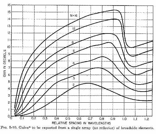
If the array is expanded, additional cells like this are built. These cells are connected in groups of cells, and eventually in layers of branches containing cells, with branch or splitting points fed through equal length feeders from common matching points. This feed method is the most stable in weather and feeds the elements in phase regardless of line length, velocity factor, frequency, or impedance so long as the two equal length lines are the same type. This array can also be oriented so the elements are vertical. Years ago I had just such a vertically polarized array for 20, 15 and 10 meters. It was one of my better working curtains. It was much better than my bobtail curtains, and performed better than a Bruce array in on-the-air comparisons. It also worked three bands, not just one! Lazy H Antenna and Distributed-feed Curtain ArrayThe Lazy H is actually two stacked dipoles fed in-phase. The gain varies with dipole length and spacing, but through proper feed techniques and antenna size the array can be made to operate with gain and good pattern over nearly a 2.5:1 frequency range. Let's look at a 3.5 MHz to 7 MHz Lazy H. (This could of course be scaled to 28 MHz, so we can consider 7 MHz as 28 MHz and 3.5 as 14 MHz with proper size scaling.) First we would set the element length and spacing for the highest frequency. We do this by making each element an extended double Zepp, or a 1.3 WL long center fed doublet. For 7.1 MHz we would have: 984/7.1 = 138.6 feet for one wavelength 138.6 * 1.3 wavelengths = 180.2 feet doublet length This length is the approximate maximum collinear length. The actual optimum length will be slightly shorter. Now we know the absolute maximum length elements can be. To find optimum spacing we can look at the graph on my Broadside and Collinear gain page.
Optimum gain for two broadside elements occurs near a spacing of .65 to .7 wavelengths. We want to use the maximum broadside spacing possible at the highest planned frequency before gain falls off to ensure the best low frequency performance. This will also be the minimum height of the lowest element above ground if we want near-optimum gain on the highest band. .7 wavelength * 138.6 feet per wavelength on 40 meters = 97 feet minimum height for lowest element on 40 meters. This means we need two "dipole" antennas up to 180 feet long stacked up to 97 feet apart with the bottom element 97 feet above earth for a maximum frequency of 40 meters. (This is, through no accident, as close as I could get to that height and spacing for my stacked 40 meter beams.)
1 is the upper "dipole" element. 2 is the lower element. Each are 180 feet long and fed with 450 ohm lines in phase at point 3, the feedpoint. feed line lengths are not critical because this is a distributed feed from one central common point. Modeling the Lazy H with an element length of 180 feet and element heights of 97 and 194 feet, we have the following patterns:
The antenna above produces an overall gain of 14.6 dBi, or 14.6 - 8.5 = 6.1 dBd This antenna has 6.1 dB over a dipole at optimum height. This compares to only 3.4 dBd gain for the twisted feed method lazy-H shown at the start of this article. With only a feed method change and a slight increase in spacing, gain has almost doubled! At 5.4 MHz we have:
13.44 - 8.5 = 4.94 dBd almost 5 dB over a dipole at optimum height. We now have improved gain-bandwidth significantly!! Now let's change the frequency to 3.5 MHz, with no changes in the antenna:
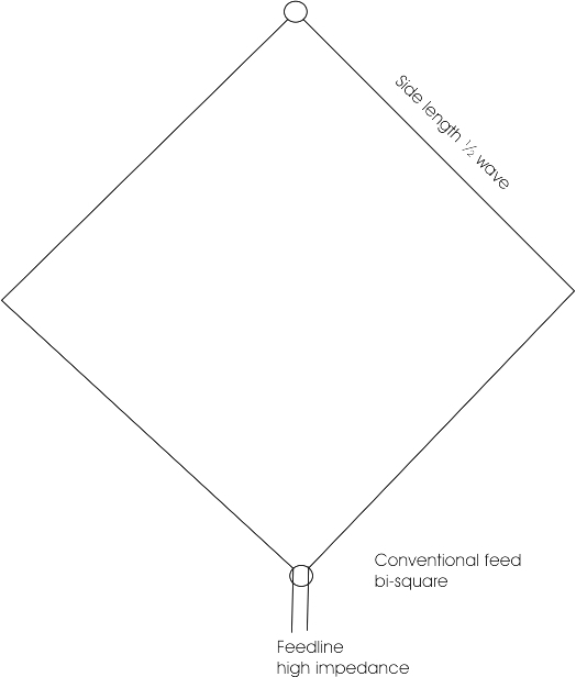
We have 9.21 dBi, or 0.71 dB gain over a dipole at optimum height. This isn't much gain, but at least it is not significant negative gain like the twisted feed antenna produces at half-frequency!! By using two equal-length open wire feed lines to a common junction, and feeding that junction with another open wire line to a tuner or matching system, we can have a gain antenna over a 2:1 frequency range (and beyond). This is the basic principle of distributed feed broadside arrays. You cannot do this with a transposed feed line or a series feed system. It just will not work if you want gain or good performance on multiple bands. You cannot do this with a Sterba curtain either, since a Sterba is a narrow bandwidth antenna when we consider gain and pattern. Bi-Square ArrayThe bisquare array is actually a single support lazy-H antenna. This makes the bisquare antenna very easy to install, requiring only a single center support. Instead of having the elements perfectly horizontal like most collinear/broadside antennas, the bisquare has V shaped elements. While a series feed is often shown, the bi square antenna can actually be fed either with the superior broadband distributed feed system, or the easier but very narrow gain-bandwidth series feed system. The standard narrow bandwidth series feed does not use a vertical balanced transmission line like the lazy-H antenna. The more popular narrow bandwidth series-feed system uses the elements themselves as the transmission line. While this eliminates some open wire feed line, it does not result in maximum performance.
This antenna does not quite have the gain claimed in many books and articles. Those articles assume Lazy-H caliber performance, but the bisquare doesn't quite match performance of a Lazy H. The bisquare is a folded in Lazy-H. Folding the lazy H in allows much easier mechanical construction, but the folding narrows array width (collinear spacing) and element stacking spacing (broadside spacing) substantially. For example, on the band where each side is 1/2 wave long a lazy-H antenna would have 1/2 wave stacking distance and 1/2 wave collinear distance between current maximums. When we fold the open ends of the lazy-H together to form a bi-square the stacking distance is between current maximums is only 127 degrees electrical and the collinear distance between current maxima is 127 degrees. This is the electrical equivalent of a lazy H antenna with 0.7 wave long dipoles for each element (0.35 wave collinear separation between current maximums) and only 0.35 wave stacking distance between the dipoles on the primary band. Shorter stacking spacing of current maximums causes the bisquare antenna to lose most of the stacking gain available in the lazy H, and much of the collinear gain developed in the lazy-H. This is why the bi-square, even with optimum feed, has about half the gain of a lazy H antenna. This doesn't mean it is a bad antenna, it will work quite well on at least two bands with the distributed feed system. The mechanical simplicity of the bi square's single support often has more value than maximum gain.
The antenna to the left is a more common bi-square antenna feed method. This feed system results in a series-fed antenna. The upper inverted-V element obtains its power from the connection to the outer-end of the lower V element. This antenna only works well when each side (or face) of the diamond's four faces is 1/2 wave long. This results in a total of two wavelengths of antenna wire. This feed method suffers the same electrical spacing issues at the current maximums as the distributed fed bi-square, except outside of the design band the phase and location of the current maximums is wrong. This current location and phase shift error prevents the antenna from having a good pattern over wide frequency ranges. If we find a way to electrically short the upper insulated break in the conductors on half-frequency, this bi-square will act like a conventional full wave loop on half-frequency. One way to do this would be to connect an open stub at the top that is 1/2 wave long on the band where the face lengths are each 1/2 wave long. In this case when frequency is moved to half frequency and each side is 1/4 wave long, the upper inverted V element is shorted. This makes the antenna behave like a full wave loop on the half-frequency, and behave as a bi-square on the primary design frequency. The voltages across the open ends can be very high, many kilovolts at high power levels, so this system requires a good relay or stub even at low or medium power levels.
The patterns below compare conventional feed bi squares with distributed feed bi-square antennas. Bi-square PatternsDistributed feed 7 MHz bi-square patterns for a 138-foot high distributed feed W8JI style bisquare. This antenna is a "square" 68 feet on each side, for a total of 272 feet of wire. The upper two wires apex is at 138 feet:
The bi-square above has 10.34 -8.5 = 1.84 dBd gain. Increasing height only has a minimal effect on gain on 40 meters (the higher band). For example, at 200 feet apex height the 40 meter gain only increases 3/4 dB over performance at 130 feet. The 80 Meter pattern of 40 meter distributed feed bi-square is shown below:
The 80 meter gain is about 2 db negative from an optimum height dipole, but increased height will help 80 meters. Let's raise the height to 200 feet apex height...... Distributed feed bi-square on 80 meters, apex 200 feet::
With the antenna at 200 feet apex height, we now have about the same gain and pattern as a dipole at 150 feet Conventional feed pattern on 80:
Conventional feed distorts the pattern and produces about -4 dBd gain on 80, making this a lossy antenna on 80. With increased height 40 meter gain and pattern of distributed feed has changed to this:
We now have about 2.6 dBd gain on 40 meters, up about .75 db from the 138 foot high bi square. Looking at the same antenna with conventional feed we have:
We have identical 40 meter gain, about 2.6 dBd gain on 40 meters with conventional feed.
On 30 meters with distributed feed we have the following pattern:
Here we have 9.5-8.5 = 1 dBd gain on 30 meters with distributed feed. The azimuth pattern is fairly clean, but starting to show a cloverleaf pattern from the elements being slightly too long. With conventional feed we have the following 30 meter pattern:
We now have about .3 dBd gain on 30 meters with conventional feed, a loss of .7dB peak gain but the gain it has is mostly at a very high wave angle. The bi-square antenna is obviously a compromise from the Lazy-H array. The peak gain of a bi-square with optimum feed is only about 2.5 dB over a dipole at optimum height, while a Lazy-H would be about 3 dB higher. With distributed feed it can be used on three bands, but it isn't a high gain antenna on any band. While the bi-square has about the same gain as the conventional transposed-feed lazy-H antenna, it is about 3 dB down from a distributed-feed lazy H antenna with optimum spacing. Collinear or Stacked BiSquare or "BiQuad" Antennas Bi-square antennas, like Lazy-H antennas, can be expanded into a larger array by using proper expansion methods. We must be mindful that series feed, while simpler in construction and less expensive narrows bandwidth significantly, degrades pattern, and decreases system efficiency.
Base antenna, 40 meter bi-square 70 feet on a side with 140 foot center height:
Basic monoband antenna has 11.04 dBi gain, or about 2.6 dBd gain.
By adding a second element collinear, we have:
We now have 13.1 dBi, up from 11.04 dBi gain. This is about 2 dB additional gain, or about 4.6 dBd (dB over dipole) gain.
In similar fashion, one antenna can be stacked above the other vertically. This does not quite produce the same gain increase. As a general rule we are better off using the multiple supports to build an H antenna.
Feed Methods Dual-bisquare There are numerous methods of feeding dual bi-squares or double quad antennas, some of which result in vertical polarization and some of which result in horizontal polarization. The widest bandwidth systems are distributed branched feed systems, while the most simple would be a series feed near the center.
Lazy H Antennas Transposed Feed and Distributed FeedThe next logical step in the Lazy H, other than adding a reflector, is to expand either the stack height or the stack width. Let's look at width first, but let's also keep in mind a reflector at this point would add over 3 dB gain. Making the Lazy H two bays wide we have:
Pattern width becomes narrower, and we have 9.35 dBd gain on 40 meters. This would be a bit more than 3 db higher if we made it unidirectional, or over 12 dBd gain. This would be MORE gain than a pair of 4-element Yagi's stacked at optimum height! On 80 meters we have:
Which is 4 dBd gain on 80 meters. We have the approximate gain of a two-element full size Yagi, except it covers the whole band and well beyond with increasing gain as we increase frequency! Again if we added reflectors, the gain would exceed 7 dBd or be about the same as an optimum 4 element Yagi. One notable difference is the curtain would cover ALL of 80 meters, not a small portion of the band. The next step could be to narrow elevation pattern by adding an upper element. This is a three high stack two bays wide or an HR 32 array (HRS if steerable).
The 40 meter gain is now 10.8 dBd. This is more than a stack of full size three-element Yagi antennas. On 80 we have:
We now have 5.8 dBd on 80 meters, better than nearly all 80 meter Yagi antennas. Again if we add a reflector system, the system would have around 9 dBd gain. This is better than any stack of 80 meter yagi antennas in existence. The final step was to add a reflector screen 35 feet behind the array; although this screen could have been added anytime in the process to pick up at least 3 dB. This "screen" only needs to contain horizontal wires. Resonant reflector wires, one 35 feet behind each dipole element, would also work. We now have:
The 40 meter gain is now 13.9 dBd, which is virtually unheard of gain in an amateur station at HF. With 1500 watts, this is like running 37 kilowatts into a high perfect dipole. On 80 meters we now have:
On 80 meters we now have almost 8.5 dBd at the bottom of the band, climbing to 9 dBd at 3.8 MHz. This is about equal to a stack of full size three-element Yagi antennas, except it will work on any frequency from 3 to 7.5 MHz with increasing gain as frequency is increased. This is a properly working distributed feed (USIA/VOA style or HRS style) curtain. While the operating SWR bandwidth is not as great as with Rhombic Antennas, the curtain antenna can easily have significantly more gain than the very best Rhombic designs. It does this while occupying a tiny fraction of the Rhombic's physical space. Note, this is NOT a Sterba curtain!! VOA did not use Sterba curtains. Look at pictures, and you will see VOA actually used distributed feed arrays. Let's look at why they did NOT use Sterba curtains in the text below. Sterba CurtainThe Sterba curtain antenna is sometimes misspelled sturba curtain. The Sterba curtain is in the same antenna family as Bruce arrays. They are series fed antennas, where outer elements obtain power from a long series path through all conductors closer to the feedpoint. (You can read about distributed feed curtains in Jasik's "Antenna Engineering Handbook" as well as here.)
Please note:
There is a large difference between distributed
feed or branched feed curtain arrays like USIA arrays and Lazy H antennas and
narrow or single band curtains like Sterba, Bobtail, and Bruce arrays. The
Bobtail isn't even a
true curtain array
in the class of
high gain
curtains. The
Bobtail is a simple three-element
vertical broadside-array with a unique feed system that produces binomial current
distribution, but it
is still commonly
referred to as a
curtain.
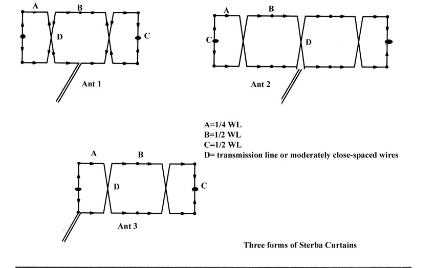
Many people incorrectly call USIA or distribution / branch-fed curtains "Sterba curtains". Factually there are HUGE differences in performance and construction of broadcast curtain arrays like the USIA arrays used at VOA and Sterba curtain arrays. Because the Bobtail isn't a true curtain (and doesn't have the potential for significant gain), I won't include them in this discussion. We are actually installing a large USIA style or distributed feed Curtain here at W8JI. You can see the new tower that will eventually support one end of the curtain at this link. The planned curtain at W8JI will be aimed at Europe, it will have a reflector, and will cover both 80 and 40 meters. The upper element will be 300 feet high! This antenna will have about 18dBi gain on 80 meters, and almost 23dBi gain on 40 meters. Sterba Curtains Sterba curtains are modest-gain single-band antennas. They are named after EJ Sterba, who developed a simple curtain for Bell Labs in the 1930's. There are multiple feed arrangements for the Sterba. They provide a very limited gain-bandwidth product and are critical to construct. You can find details of Sterba curtains in William Orr's Radio Handbook. Let's look at an actual Sterba array so we can understand why Sterbas have narrow bandwidth and limited gain:
Let's walk through the current distribution of Ant 1.
This poor method of excitation produces three very undesirable circumstances:
The amateur radio fascination with Sterba and Bruce arrays probably stems from confusion. I've noticed most amateurs incorrectly call large distributed-feed or branched-feed curtains used by short wave stations "Sterba" curtains, but they are definitely not!! The Sterba and (if ground conductivity is high enough) Bruce arrays can be good antennas, but they are frequency sensitive and require careful construction. I can't recall ever seeing an actual Sterba curtain used at any commercial SW BC (shortwave broadcast) station. Distributed or Branch Feed curtains are used, not sterba arrays. These distributed feed curtains are also called HR arrays, with the H and R standing for Height and Rows. When they are steerable, they are sometimes called HRS arrays, the S representing "steerable". An HR 43 would be an antenna 4 elements high and 3 elements wide. If it was an HRS 43, it would be a steerable array of the same element configuration. Sterba Curtain ModelThe following is a model of a center-fed Sterba. This antenna is identical to the one on HamUniverse (link to models of this antenna), except this antenna is properly scaled for 40 meters. Height above ground of bottom wires 16,12, 3, 7 = 67 feet height at bottom. 134 feet high at top. Length of 1/2 wave wires 3, 4, 6, 8, 9, 12, 13, 15, 17, 18 = 67 feet Length of 1/4 wave wires 2, 5, 7, 10, 11, 14, 16, 19 = 33.5 feet Fed in center
Pattern of correctly dimensioned 40-meter Sterba curtain antenna using REAL open wire line for vertical sections (not window ladder line).
Source impedance
on 7.1 MHz is 69.92
- J 8.59 ohms Gain is 12 dBi or
3.6 dBd. This large
complex antenna has
3.6 dB gain over a
dipole on the design
band at optimum
height. This is
actually about the
gain of a simple
double extended Zepp
antenna.
This antenna now has 6.8 dBi gain, or about -1.72 dBd gain. It has almost 2 dB negative gain over a dipole. This is quite different than a properly fed Lazy-H or other distributed feed curtains! Feed impedance on 80 meters is 8.166 - J 35.29 ohms SWR (50 ohm system) = 9.229 (75 ohm system) = 11.238 On double the design frequency, in this example 14 MHz, it has the following pattern:
This is a very poor multiband antenna. It has about the same gain as an extended double Zepp on the design frequency, the gain of a dipole on the second harmonic, and about -1.7 dB negative gain over a dipole on half-frequency. While this antenna can be loaded on multiple bands it is NOT a multi-band curtain.
Sterba Gain vs. Ground SystemClaims have been made a ground system will increase gain 3-6 dB with a Sterba curtain. This is not true. The only possible change a ground can make to a balanced antenna, such as an array of doublets making up a curtain, is to reduce induced or coupled losses in earth by "shielding" the earth from the intense fields of the antenna. It is true that a very low dipole (low means a small fraction of a wavelength) can benefit greatly by the addition of a grid of wires parallel with the antenna below the length of the antenna. For example a dipole at .05 wavelengths above ground could show several dB increase in field strength when a ground screen or system of wires are laid parallel with the antenna element. The effect is caused by the reduction of current in the lossy soil. The overall efficiency of the antenna can increase so the pattern has increased intensity at all angles and directions. This effect is significant only for very low antennas. It does not apply to a curtain at any reasonable height. If the antenna is so close to earth as to benefit significantly from a ground screen, then it would be definition be a very poor array to start with. Let's look at the curtain first:
Average soil pattern of curtain Perfect zero loss ground pattern of same antenna Net gain difference 0.53 dB by adding a perfect zero loss ground in all directions for infinite distance. That isn't much change!
Dipole at 1/10th wave high over medium dirt Dipole at 1/10th wave high over perfect lossless groundplane Low dipoles can have a significant change, in some cases over 6 dB, with the addition of a large reflective ground screen below the antenna. There is almost no change in antenna pattern, but the antenna efficiency increases a great deal.
The Bruce array is a vertically-polarized single-band curtain antenna. The primary advantage of the Bruce array is a relatively low height requirement. With Bruce array elements being only 1/4 wavelength tall, 3/8 wave tall supports will often provide adequate overall height. Each element is fed by the wire in preceding elements, all connected in series. With series-fed arrays on lower frequencies, current has to flow a considerable distance through conductors, sometimes hundreds of feet. Because of this series current feeding, system efficiency decreases with physically longer antenna lengths. This is particularly true with higher RF resistance conductors, and with lossy earth close to conductors. As the array is made longer, gain-bandwidth becomes narrower. This is because the antenna elements become transmission lines, with multiple 1/4 wavelength sections in series. Any error in each section adds, several elements with only a few percent error can add to significant phase errors at the ends, and significant feedpoint impedance mismatch. As progressively more sections are connected in series, length errors and losses continually add. This limits how large the array can be, before efficiency and pattern diminish. As with all vertically polarized antennas near earth, the Bruce array is seriously impacted by soil conductivity in the Fresnel region (Brewster effect in the area out a few wavelengths to several wavelengths from the array, where pattern is formed).
Bruce Array over infinite, lossless ground
In this array, wires 1 and 9 are 1/8th wave long, counting end-effect. End-effect, from the high voltage electric field abruptly terminating at the open end, shortens the required physical length of end wires 1 and 9 slightly. All other wires are 1/4 wave long, assuming bare wire. This is because, on inner sections, high voltage points are away from insulators, and high voltage center sections continue on with minimal electric field fringing. This four-element Bruce array model includes copper losses. Gain over a 5/8th wave high reference dipole is about 3 dB, although wave angle is significantly lower. This 3 dBd gain would be representative of a four element Bruce array over saltwater.
Bruce Array over real medium earth
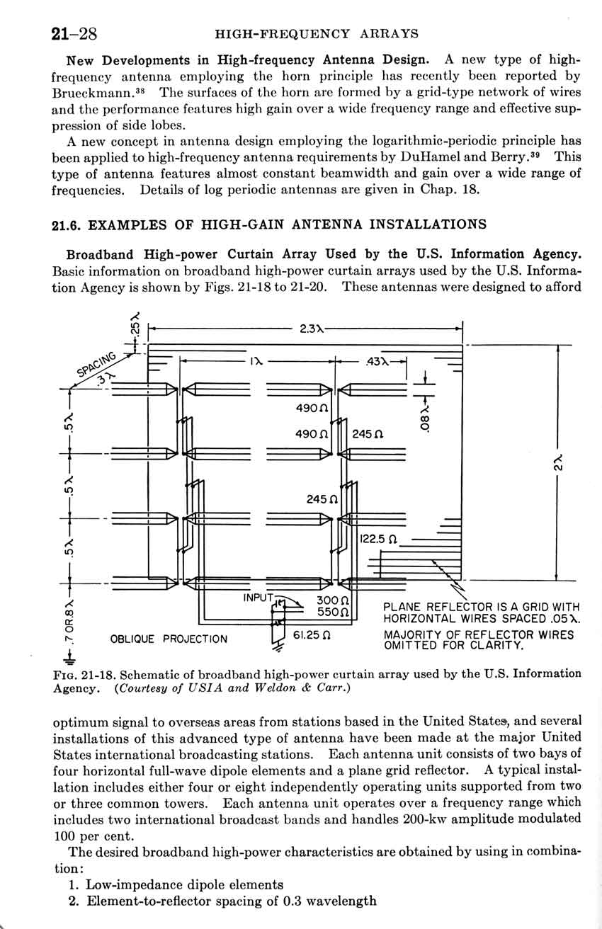
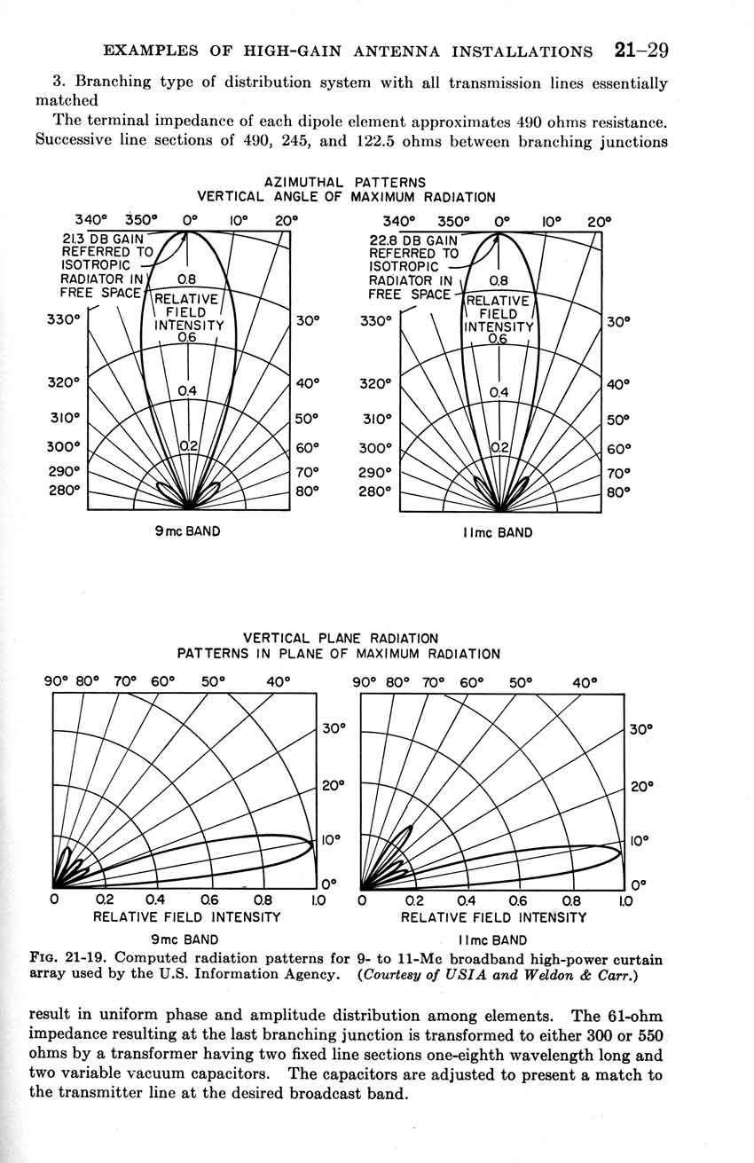
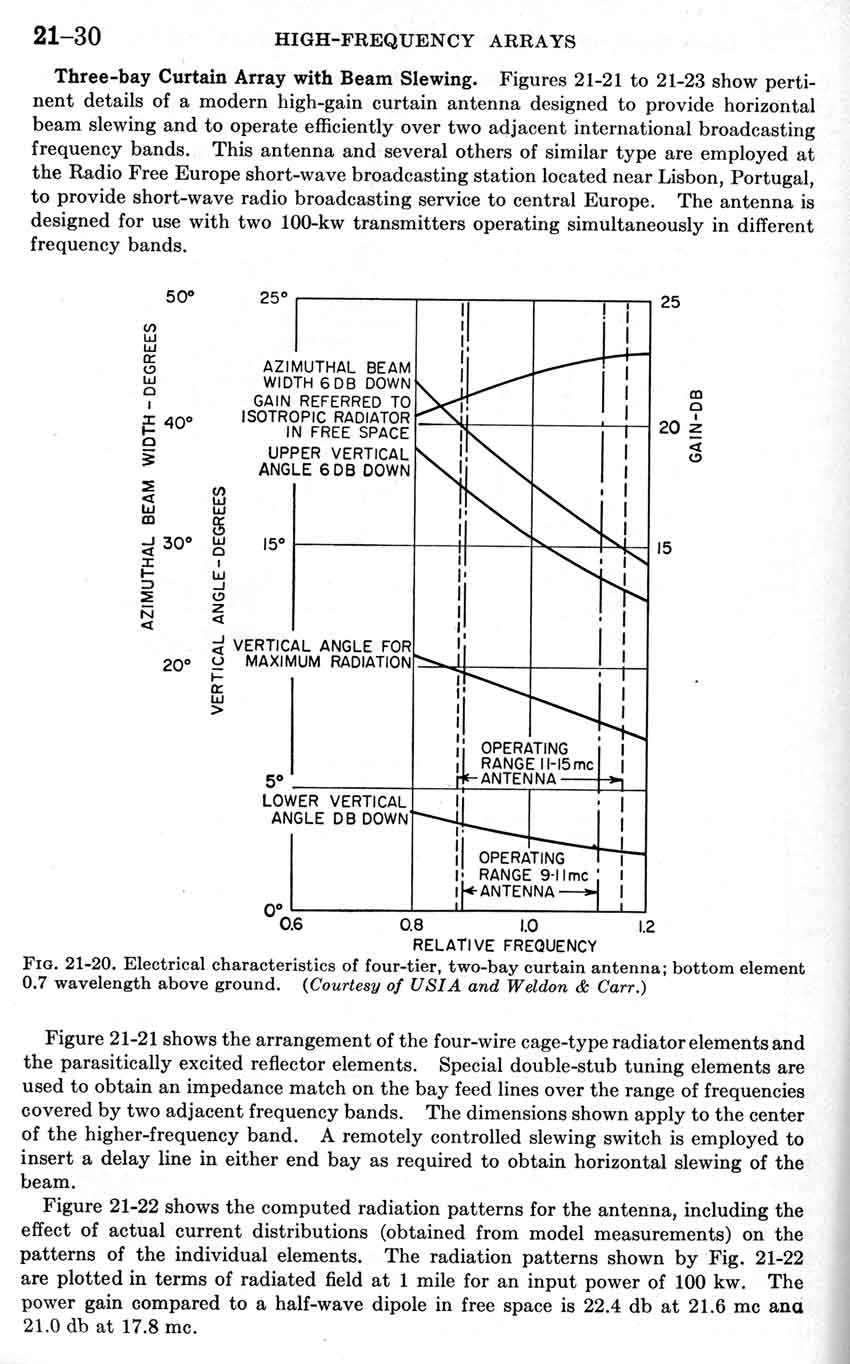
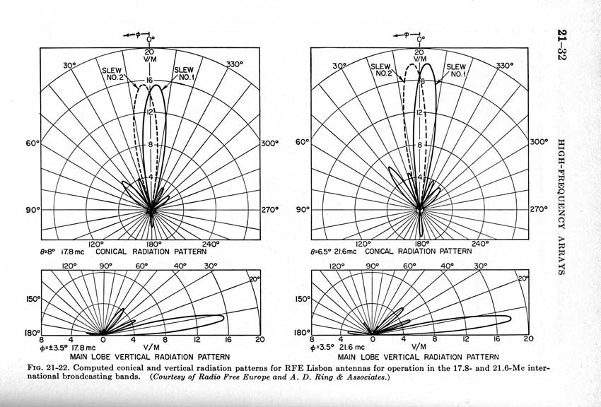
Things change significantly when real earth is involved. In this case the Bruce array has about -3 dBd gain. This is why I had a difficult time justifying my 75-meter Bruce array, installed in the early 1970's. My Inverted Vee dipole at 130 feet was about even with the Bruce array into Europe night-after-night on 75 and 80 meters. If you have high ground conductivity, and cannot install a dipole antenna very high above earth, the Bruce antenna shows some merit. The Bruce antenna has reasonable gain over a standard omni-directional vertical. With an extensive counterpoise system below the antenna, it is possible to pick up a few dB of gain over poorer soil types. An extensive counterpoise system can increase overall efficiency from 25% to about 40%. Summary, USIA, or Distributed/Branched feed-system CurtainsDistributed feed curtains use a series of common points, each fed from equal length low loss transmission lines, to distribute power. Conductor loss is less, phase error is significantly reduced, and all elements receive equal currents. This feed method places conductor resistances in parallel, and makes array patterns stable over very wide frequency excursions. In addition to having more gain, a distributed feed curtain (such as USIA arrays used at VOA sites) can be used over a 2:1 or broader frequency range with minimal gain and pattern change. It is very easy to make a distributed feed curtain operate on 80 and 40 meters with full gain and no pattern distortion. A distributed or branched feed curtain also allows designers to use optimum element spacing, both in collinear and broadside (stacking) distances. This means a 4-element branch fed curtain can provide the highest gain per acre of any antenna design.
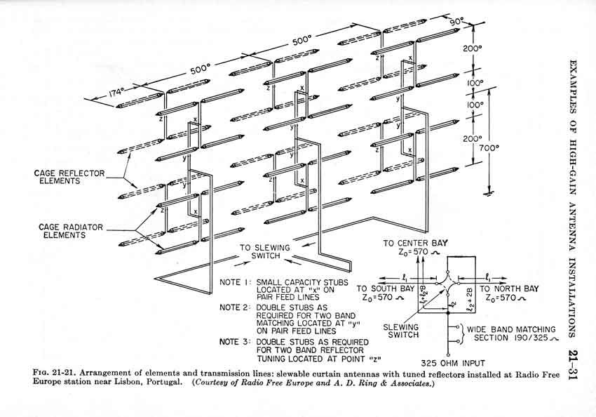
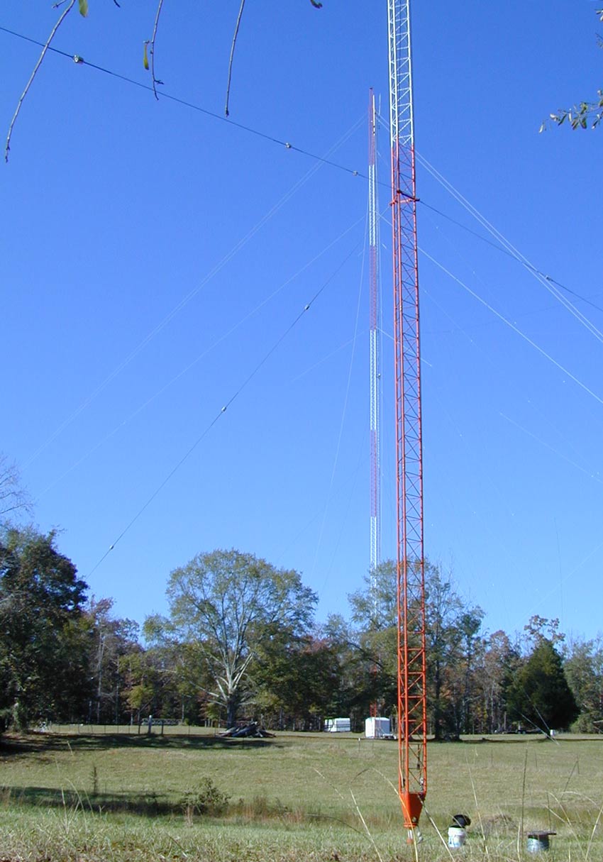
Despite occupying a tiny fraction of the space required for their rhombics, the USIA style curtains are the highest gain arrays used at VOA's International Broadcast and the largely defunct VOA relay sites. Note: The Lazy H, when center fed, is a distributed-feed or branched-feed curtain. The antennas below are similar to my planned 80/40 meter antenna. Since I am not running 100 KW AM transmitters, I'm not worried about element voltages or open wire line arcing. I'll use single wire elements instead of wire cages and operate low loss open wire lines with standing waves. This simplification is acceptable for amateur use because voltages and currents are much lower with 1500 watts CW or SSB rather than 100 kW or more carrier power (400 kW PEP on AM) used by VOA. My curtain will have the upper element at 300 feet, and the lowest element at 100 feet. It will be three layers high and three sections or "rows" wide. Another name for the array, in common SWBC descriptions, would be an HRS 3/3/1 array. This is a Height Row Steerable 3/3/1 array. My variation models just over 18 dBi on 80 and over 23 dBi on 40 meters, with ability to steer the beam in azimuth and elevation. I've had similar scaled down distributed feed curtains for 20 meters and up in the past, and they worked quite well. Unfortunately I don't like 20 meters and up, so I only used them as a brief experiment lasting a few months. By the way, curtains like this have considerably more gain than Rhombic antennas. The curtain would also occupy a tiny fraction of the space required by a Rhombic producing significantly less gain. For example, my planned 80/40 curtain is only 350 feet wide and 300 feet high yet has almost 15 dB gain over a dipole on 40 meters. A 1500 watt transmitter into the curtain will produce the equivalent of 37 kW to an optimum height dipole. Of course this all hinges on getting new 300-foot Rohn 55G and 320-foot Rohn 65G towers installed, which is actually more than 50% complete now. My Curtain Array
This is an HRS 331 array. There are three bays high, three bays wide, and the system is steerable in elevation and azimuth. The upper element is at 300 feet, and the array is about 350 feet long with 30 foot spacing to the reflectors, allowing simple 30 foot long booms from Rohn 25G to support the elements at the proper spacing. You might wonder how I can get away with fewer wires in the elements, and reflectors instead of large complex screens. The multiple conductor elements in a SWBC array limit impedance changes as frequency is varied, and the also keep voltages low. This is very necessary when transmitters run ten's of kilowatts on AM.
For Amateur use, neither of the above is problematic. Power levels are low and the system operates on two or three fairly wide spaced bands. This allows the use of resonant reflectors. Here are a few pages my planned system is derived from: Basic curtain with reflector. In amateur applications it is possible to use a system like this over a 2.5:1 or wider frequency range! The system can also be scaled down to use fewer elements, and the reflector can be omitted. You can see the tower being installed that will support one end of this curtain on my Rohn 65G page.
|


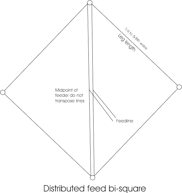 The antenna to the
left is a
distributed feed
or W8JI
bi-square. This
antenna will have a
broadside pattern
with equal or better-than-dipole
performance on frequencies where
each one of four sides of the diamond making up the antenna are between 1/4 and
5/8 wave long.
The antenna to the
left is a
distributed feed
or W8JI
bi-square. This
antenna will have a
broadside pattern
with equal or better-than-dipole
performance on frequencies where
each one of four sides of the diamond making up the antenna are between 1/4 and
5/8 wave long.