
Ground Loops Audio
Systems
How Ground
Loops Occur (technical)
| Note: This discussion only applies to grounds within a platform or system. It does not apply to cables or wiring outside a building, where lighting damage or other surges are concerns. |
Ground loop problems
usually occur when interconnecting ports are grounded
to points operating with
voltage differences. The voltages differences are generally created by high currents
in another grounded path. The problematic voltage differences are commonly created by
voltage drop along a
high current conductor that is ground at both ends to a common ground. This can
create a potential difference along a signal wire ground path, and that voltage
is transferred into the sensitive circuit.
The unwanted interaction we call a "ground loop" is generally an unintentional
result from poor wiring techniques, poor source or load port planning, or a
combination of all.
Note: "Port" by definition is
a signal input or output connection, usually via a jack, connector, or terminal
strip. "Ports" are the interconnect point where an interconnecting wire or cable enters or leaves
a device.
Using a ground bus along a desk does not cause a "ground
loop". Changing wires to a star or running individual ground wires to a distant
common point, like a rod, does not correct ground loops. Multiple ground leads
to a distant point does not
correct ground loops or RFI except through pure luck. Long isolated ground leads
from equipment on a desk to an off-desk common point like a rod isn't good
science.
Equipment low frequency or DC ground loops are caused by power
cable voltage drops and by not using single point grounds at one end of the path. RFI is caused by common mode RF
on antenna cables or flawed shield integrity. The shorter and lower ground connection path
impedance between equipment at one point, the better! The exception is
generally any high current power source or load. High current sources or loads generally
should NOT be tied to
the ground bus at more than one point. Something like a high current power
supply negative lead should only be be tied to ground at the equipment end.
Ideally the negative bus would float at the supply, but have a safety clamp that
is a high impedance under normal conditions while limiting negative terminal
rise under faults.
With the
exception of a high current power supply with a chassis grounded negative, which
should be grounded directly to and only at the high current equipment it serves, the
shortest lowest resistance path between equipment is always best. This
generally mandates a heavy low resistance bench ground bus with short flexible
braided leads connecting desk equipment to that bench bus.
Negative lead
fuses on equipment is also generally a bad idea, yet we see it everywhere.
Negative lead fuses were made necessary because of poor wiring instructions!
Modern vehicles use a microprocessor system to learn many aspects of engine conditions. The processor reads outside sensors, and using that data, calculates spark timing, fuel injector opening windows, activates pumps and fans, controls EGR, adjusts engine idle speed, and dozens of other functions. Multiple sensors tell the computer dozens of parameters ranging including throttle position, air mass flowing into the engine, coolant temperature, barometric pressure, exhaust oxygen content, crankshaft position, and other parameters. The difference between supplying fuel for 15 horsepower or supplying fuel for 500 horsepower can be less than 3 volts change on some sensors! Tenths of a volt change can significantly alter critical engine parameters, and sensor changes in the hundredths of a volt can alter mixture a noticeable amount. This sensitivity to relatively small sensor voltage changes is the root of engine control ground loop problems.The key to properly controlling complex functions is reading high-impedance low-voltage sensors, generally operating in the range of zero to five volts, accurately. Noise can especially hurt accuracy in sensitive timing functions.
Equipment damage can result from ground loop issues. Because of dense packaging and miniaturized construction, modern electronics uses small conductors (foil traces) and components. A ground loop can melt foil traces, damage semiconductors or chips, or destroy small resistors. A ground loop can ruin an expensive electronics system in a fraction of a second. Even worse, a ground loop affecting fuel metering or spark timing can destroy an engine.
My problems with an aftermarket EFI system are a good example of a ground loop error threatening engine life.
High sensitivity to small voltage levels is at the root of audio ground loop noise or hum issues.
A secondary issue is equipment damage. Because of dense packaging, modern audio electronics often uses small foil trace conductors and current sensitive components. Low power semiconductors can be irreparably damaged by a few volts or a few thousandths of an ampere current. As with home computers and cars, a ground loop can melt foil traces, damage semiconductors or chips, or destroy small resistors or capacitors. An expensive audio component can be ruined in a fraction of a second.
In my early days of broadcast engineering, ground paths between different pieces of audio gear were isolated. Engineers grounded shields on balanced lines at one point in the path, generally at input port terminals. Shields on unbalanced lines, unless equipment was mounted in the same rack were floated by an isolation transformer at one end.
The only common chassis connections were power leads, radio frequency grounds, and safety grounds. Audio or low-level signal ground shields were always isolated from chassis or earth paths at one end. This was universally true for all low-level signal lines. The isolation prevented unwanted ground loop signals, commonly appearing as hum or noise, from producing low-level background trash. It was very poor practice to dc chassis ground both balanced and unbalanced lines, especially lines with shields less than several skin depths thick or excessively resistive shields, at more than one point in a cable run.
Low-level analog metering and signal grounds are also upset by ground loops. Generally, at least one end of a run should be ground independent or ground isolated. This will prevent ground loops from upsetting critical signal voltages and producing false readings.
The most basic ground loop is shown below:
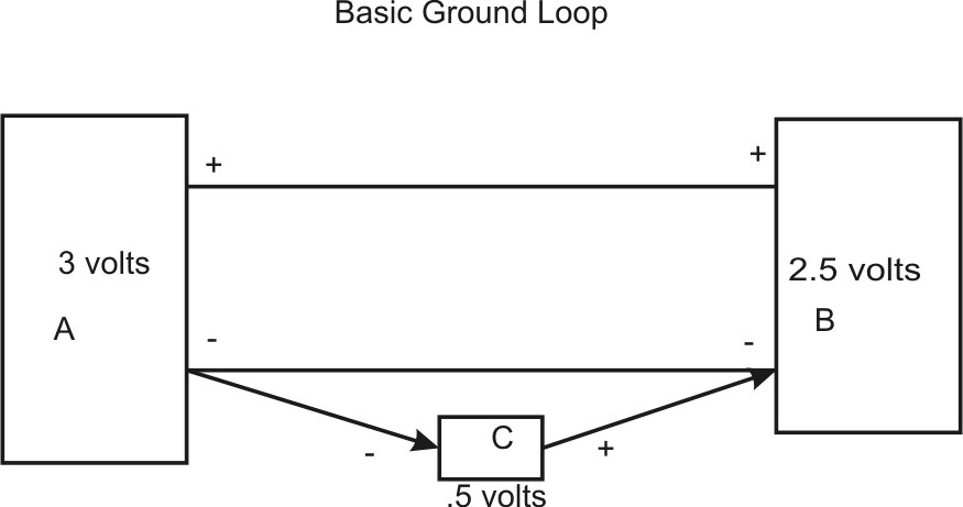
If we consider a direct current system with "A" as a source and "B" as the load, voltage "C" will push "B - " up by .5 volts. This means the differential between "B's" plus and minus will be 2.5 volts.
Conversely, if "B" was a 2.5 volt source source and "A" the load, "C" would push "A -" more negative and "A" differential between + and - would be 3 volts.
This is why we have to be sure nothing forces an external voltage across a ground lead. The only way to eliminate the chance of a ground loop disturbing a sensitive voltage, or even causing damage, would be to float one or both ends of the system completely from ground. At least one end, either the source end or the load end, has to be in differential mode. "Differential" means only concerned with voltage difference between + and - and not an external source. Placing one end in differential makes it look like this:
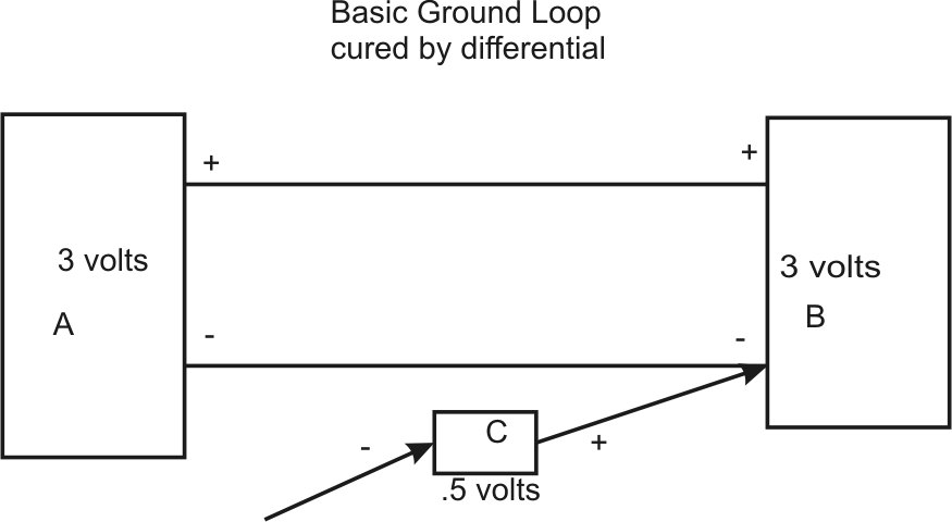
In the above case "B - " would have the only ground point. There could be no ground at "A -" . Ungrounding either end's negative and making the load or source differential cures the ground loop.
Curing a ground loop problem by making the ground conductor larger is generally not the best way to do things, although it certainly can help by reducing voltage drop (making path impedance lower). The problem is conductors, no matter how large, always have some unavoidable voltage drop with current. This voltage drop is determined by Ohm's law, where current times resistance is voltage drop along a current path. If the conductor carries high frequency signals, the issue is complicated by impedance and standing wave effects. For most audio, power supply, and control systems we can just consider resistance. For higher frequencies or sharply rising waveforms (like ignition system pulses), we have to consider the reactive parts of wiring impedance.
Systems with a mixture of large currents and sensitive low-level lines are much more troublesome than other systems. High currents can easily create voltage drops that are a significant portion of the low signal levels. When the high current and low level systems share grounds, the high current voltage drop along ground or neutral wiring can be transferred to other ground paths. This transfers a portion of the high current into the low level system.
In the circuits below, even with thousandths of an ohm conductor and connection resistance, the high current ground path has over 1/10th of a volt drop. The signal lead, even with much smaller wire, only has a few millivolts drop. This is because load current is very low.
Let's look at a few basic unbalanced systems. In these circuits:
| R1 through R4 | signal wire and connection resistances |
| R5 | indicator or load resistance |
| R6 | High current load |
| R7-R10 | High current load conductor resistance |
| Vs1 | Source for signal |
| Vs2 | Source for high current load |
In the system below, we see signal voltage unaffected by anything except a small voltage drop in signal conductors. There is no high power load current and no ground loop.
In the system below, a common ground wire between upper and lower neutrals was added at the left end. We see signal voltage unaffected by anything except a small voltage drop in signal conductors. There is no ground loop and no high power load current. The low level sensor reads only .004 volts off from the source.
In the system below, we see signal voltage unaffected by anything except a small voltage drop in signal conductors. There is 118 amperes load current in R6, but the current does not affect the signal voltage because the signal ground lead has only one ground point. There is no ground loop.
In the system below, we see signal voltage is grossly affected by the high current load. This is because the above system has a ground loop. The signal wire is grounded at each end.
In the system below, a heavy very low resistance ground buss was added in an attempt to mitigate the chassis or neutral path resistance. Although reduced, signal voltage remains affected by voltage drop in the high current conductors. This example demonstrates why the better fix is avoiding ground loops, rather than attempting to mitigate ground loops through better ground bonding between system ground points.
Vehicle grounds in typical unibody passenger cars are a special situation. Mechanical construction techniques that make the platform rigid also work to form a large wide-area chassis ground path with very low resistance. The welded shell forms a very low resistance ground conductor, and is an excellent point for a common ground connection for signal and power grounds. While not zero resistance, the body shell is the closest thing to it. Using a four wire resistance measurement method, my 1989 Mustang measures less than .002 ohms from my rear battery ground to my front inner fender frame rail ground. This is the approximate equivalent of 15 feet of number 0 AWG copper wire and connectors. Much of this resistance is concentrated around the grounding lugs (before current has a chance to spread), and not over the body path. If I improved the connection points, I could greatly reduce the small resistance my system has now. This isn't really necessary, so I have not bothered.
It makes little sense to run a heavy copper negative from engine to battery when the chassis is already there and the body shell, including casually made connection losses, has less resistance than a well-made cable.
| Example of ground path
resistance: Resistance of any uniform conductor is inversely proportional to cross sectional area and directly proportional to resistivity and length. In simple words, if we double the cross sectional area of a conductor we cut resistance (and voltage drop) in half. If we double the length, we double the resistance and double the voltage drop. A number 1 AWG copper wire has an effective diameter of about 0.3 inches. Area of a circle is pi*r squared. This wire would have a cross sectional area of about pi*.15*.15 = .071 square inches. Let's assume a steel body shell is about 16 gauge, or about .06 inches thick. A one foot wide area would have 12* .06 = .72 square inches of cross sectional area. The physical cross section is about ten times larger than the copper wire's cross sectional area. The resistivity of steel is about 15 ohms per 10-6 cm. The resistivity of copper is 1.7 ohms per 10-6 cm. We can reasonably assume steel has about 15/1.7 = 8.8 times the resistance of copper for the same length and same cross sectional area. While the body shell has higher resistivity material, the body also has much greater cross sectional area. This means a one foot wide length of steel body shell, if that shell is only .06 inches thick, has about 10% less resistance than an equal path length through out copper wire. It's easy to see why a ground path through the car body, which likely is several feet wide and much thicker in many areas, is a small fraction of the resistance of a copper wire. A four foot wide area of floor pan, just .06 inches in thickness, would have a cross section of about 2.88 square inches. The equivalent copper conductor would have to be 2.88/8.8 = .327 square inches, or a diameter = 2* sqrt of A/pi, or .645 inches diameter! Equaling the resistance of a thin 4-foot wide steel floor pan with a copper cable requires a cable larger than 4/0 , and we have not even counted the help from frame rails, rocker panels, or roof paths!
|
Let's look at why Ford did a system a certain way, and how schematics can be misleading. This is a diagram of the battery cable negative on Fox Mustangs:
Correct schematic of the above:
In the system above, the negative EEC lead does not ground to the battery negative. The negative EEC actually connects to the vehicle chassis near the start relay, where it shares a common chassis ground point with the battery negative. Grounds like this only work when the battery is front mounted and done exactly as originally done. This system is acceptable because:
1.) The Mustang originally had fairly low current draw from the charge system.
2.) The block was grounded from a head to the firewall.
3.) The very short, heavy, battery lead was securely connected to the block.
Alternative method schematic for front battery to avoid ground loops:
Rear Battery to avoid ground loop and ground lead fire hazards:
Negative battery post connections:
With a rear-mount battery, there is no reason to run long negative leads from anything to the battery. The exception are certain trunk area devices with floated grounds, such as fuel pumps or other electric motors. This assumes a unibody vehicle or a large area frame ground with welded construction as a ground connection buss. In Europe, grounds to battery negative posts for communication equipment are prohibited due to fire and safety hazards.
| Device, with rear mount battery | Always permissible to neg post | Permissible but often undesirable | Never permissible to neg post |
| Amplifier with negative common to housing and jacks | X | ||
| Amplifier with negative floated from cabinet and jacks | X* | X** | |
| Electric motor or pump with isolated ground | X* | X** | |
| Ignition Box with negative common to housing or other leads | X | ||
| Power Inverter with negative common to housing and outlets | X | ||
| Power Inverter with negative isolated from cabinet and jacks | X | ||
| Radio system including stereo and two-way systems with negative common to cabinet and jacks | X | ||
| Radio system including stereo and two-way systems with negative isolated from cabinet and jacks | X* | X* |
* if near battery ** if far from battery
With a front mount battery, rugged ground-independent devices can generally be connected to the battery negative almost any way you like.
| Device, with front mount battery | Always permissible to neg post | Permissible but usually undesirable | Never permissible to neg post |
| Amplifier with negative common to cabinet and jacks | X | ||
| Amplifier with negative floated from cabinet and jacks | X* | X** | |
| Electric motor or pump with isolated ground | X | ||
| Ignition Box with negative common to housing or other leads | X | ||
| Power Inverter with negative common to cabinet and outlets | X | ||
| Power Inverter with negative isolated from cabinet and jacks | X | ||
| Radio system including stereo and two-way with negative common to cabinet and jacks | X | ||
| Radio system including stereo and two-way with negative isolated from cabinet and jacks | X |