
Also see Ground Loops
Safe Battery Installation Guidelines
This article is mainly concerned with battery ground and ground loops.
For front mounted:
For trunk mounted:
Trunk Mounted Battery Installation
| Any comments appreciated emailed to:
|
Automotive Electrical System Battery Grounding
|
A few quick notes: Voltage Automotive systems mostly use the oldest type of rechargeable battery (invented in 1859), the lead-acid battery. 12 volts is the short common slang for nominal battery voltage. It really is not 12 volts. Lead-acid cells are 2.1 volts per cell at rest, with a full charge. The six-cell 12 volt battery is 12.6 volts at full charge resting, should be over 14 volts while charging, and over 13 volts immediately after charging is removed (without any electrical load). See Electrical System Traditional low-voltage (12 volt) electrical systems use a negative ground system, the "ground" almost always being the vehicle's entire chassis. The highest current ground is to the engine block, since that is where alternator and starter currents flow. That ground has to be a very solid low resistance connection. It is a direct connection to the battery with batteries near the engine, and often via the chassis with remote batteries. A ground must always connect from the battery negative to the chassis with all battery installations. The Battery's Job A common misunderstanding is the battery supplies normal running load power. This is not correct, the alternator normally supplies all electrical energy. Of course the alternator will not support the electrical system when the engine is off, when starting the engine, and under certain operating conditions of extreme electrical loads, especially at slow engine speeds. The battery supplies power any time the alternator is unable to support the full electrical demand. The battery kicks-in instantly, even if needed for a tiny fraction of a second, because the battery directly parallels the alternator's output. The battery serves as a giant "electrical flywheel" to smooth voltage from the alternator. Just as the flywheel on an engine smoothes piston thrusts and clutch loading, the battery prevents sudden alternator surges or electrical load changes from radically changing the electrical voltage. The battery must be kept in parallel with the alternator with solid connections. On a running engine, if the battery is disconnected (accidentally or intentionally) and the electrical load or engine speed abruptly changes, or if the battery is disconnected from the system while charging, an alternator can surge to over 100-volts. The surge voltage can wreak havoc on sensitive electrical parts, including stereo systems, ignition systems, engine controls, and light bulbs. This is why anything we do to the electrical system should always be done in the context of having the most reliable battery connection possible. To avoid damaging voltage surges, the battery to alternator connection must never be interrupted while the alternator is supplying charging current or running current! "Under drive" Pulley Sets The things commonly called under drive pulleys actually slow the accessories. All electrical energy comes from the alternator (or whatever charges the battery if other than an alternator). If the alternator is turning too slow (perhaps through under-drive pulleys at slow speeds), the electrical system will run from the battery. The lack or low speed charging depletes the battery's charge. When an electrical system operates from battery charge at slower speeds or idle, the alternator loads the accessory belt and crankshaft heavier than normal at higher speeds to replenish the battery's idle charge loss. Slowing the alternator below operating charge speed levels at idle actually increases alternator drive belt mechanical load at higher RPM. This is because the alternator has to replenish battery charge lost at idle or low engine RPM. Under drive pulley systems reduce engine parasitic alternator load at idle and slow speeds, and increase alternator parasitic loading and waste horsepower at racing speeds. |
Battery Grounding or Negative Battery Supply Connections
| The only connection to a battery post
negative should be to another battery negative, the
vehicle chassis, and/or the engine block. There should never be a direct negative post
path to accessory equipment that has any sort of ground path to external
devices. The sole exception to this rule is when the equipment being connected electrically isolates or floats the negative terminal power connection from any external connections. If the negative power feed wire electrically floats from all exposed conductive cabinet parts or external wiring paths, a fused direct negative should be safe. An isolated power ground inside external equipment is the only condition where a direct battery negative terminal or post connection is safe. |
The starter and alternator are normally the two highest current devices in a vehicle's electrical system. The starter can draw hundreds of amperes, a large alternator can source hundreds of amperes. The starter and alternator ground carries the same current as the positive voltage hot leads to or from the starter or alternator.
Starters and alternators have their negatives common to their metal cases. They mount directly on the engine block or heavy engine accessory brackets, with the housing or case providing the negative terminal or negative ground connection. The ground path is through mounting hardware to the block. A normal properly fastened mounting system "grounds" the starter and alternator with extremely low electrical resistance to the engine block or cylinder head. The mechanical connection makes an almost perfect starter and alternator ground to the timing cover, block, and heads. Just be sure bolts are not against accidental insulators. Accidental insulators include anodized aluminum, power coated metal, paint, and even thread locking chemicals such as Loctite. Loctite will wick down into threads and insulate threaded joints. Never use Loctite on electrical connections. Dielectric greases, electrical pastes, or anti-seize compounds behave differently, sealing air and moisture out to prevent corrosion without harming electrical contact. They push out of the way.
The ideal alternator and starter battery ground path is through a heavy block-to-battery cable connection. A very close second choice would be a timing chain cover grounding boss or stud. Sometimes, but not always, a cylinder head or bell housing connection can be used. Generally, the fewer gaskets between the block and battery ground, and the larger the metal area and thickness at the connection point, the better the ground connection will be. Never connect directly through Loctited fasteners or against anodized, rusty, corroded, or painted parts. The vehicle manufacturer most likely selected the very best ground points.
Warning! Read this!
Battery path current can be hundreds of amperes during starting, and battery path current is easily 25 amperes or more when charging the battery. Additionally, the alternator supplies all running current for all accessories, with the battery supplying current when an alternator cannot "keep up" with load. With high currents like that, the battery post should be exclusively dedicated to the battery-to-block ground lead, and the battery negative always must have a good solid connection to the vehicle chassis.
Sharing the negative battery lead to engine bolt with anything else or connecting directly to the battery negative post with anything except the block and chassis grounds is a terrible idea. (Connecting electrical devices or hardware directly to a battery negative post is a bad idea (no matter who tells you to do it) unless the negative connection is 100% ground isolated at the electrical device.) When an electrical device is directly connected to the negative post, if the negative post to block or chassis connection opens up or develops excessive resistance, the battery negative post will divert alternator or starter current through whatever is attached to the negative post. This can be hundreds of amperes! Very few devices and wiring will suffer a fault like this without permanent damage. It is also a fire risk.
Grounding directly to the negative post is a fire hazard at worse, and an unnecessary risk to your equipment at best. Battery post connections also increase likelihood of ground loops and ground conducted noise.
On a personal note, I'm not sure why USA and Japanese manufacturers instruct people to connect things to the negative terminal. I suspect it is because they have not thought through the safety problems negative post connections create, and they somehow think a battery post provides a "cleaner" voltage or a more reliable ground because of battery impedance. Accessory or ancillary equipment battery post negative connections are banned in many countries. As a general rule, vehicle manufacturers never make a negative post connection other than block or chassis. Professional or commercial grade accessory manufacturers also do not use negative post connections. The sole exception is when a device has 100% assurance the negative bus can never contact chassis ground in any manner through any path.
The only proper and safe way to connect accessories of any type (this includes ignition and stereo systems) to the negative post is via a path through the vehicle chassis. This is not only the safest path, the chassis is the lowest noise ground path. This is why every vehicle manufacturer has a lead from negative post to chassis, and all devices other than engine block mounted devices obtain negative via the chassis or a designated ground lug referenced to chassis. This is the only safe way to do things, unless the equipment supplier and installer can 100% guarantee there will never be a negative to chassis path through the equipment.
Ground Currents and Ground Loops
All of the vehicle's normal running currents, which include ignition, radio, lights, wipers, horn, and computer systems, flow from the alternator through the engine block to the vehicle's chassis ground, or from the battery to vehicle chassis when the alternator is below battery voltage. As alternator voltage falls below 13.8 volts, the battery picks up an increasing share of load current.
Horns and lights ground to the body shell, while dashboard electronics typically ground to the firewall or the solidly welded or bolted dashboard bracing. Critical sensors and pickups normally float from ground everywhere, grounding only to the computer's internal negative bus system. The computer negative bus then grounds to the firewall or body shell. This grounding method prevents ground loops. Ground loops introduce unwanted electrical noise and/or sensor voltage errors.
A smaller very short lead from the battery negative terminal, as well as ground leads from the engine block, go directly to the body shell. These leads, primarily the heavy short battery ground lead, power all of the vehicle's grounded electronics negative terminals. The body shell, not the battery negative post, is the safest and best common ground point for sensitive electronics.
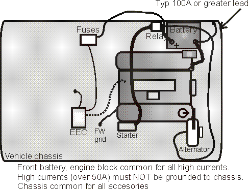
The fuses feed all electrical devices, including but not limited to lights, wiper, heater, horn, radio, and dashboard. Critical devices often run from fuse links or separated fuse or automatic reset overload limiting systems. All of these devices return through the vehicle chassis and the short battery-to-ground wire that is common with the large negative block connection wire. Alternator and starter currents are through the engine block and heavy black wire to the battery post.
The unique ground routing for different systems is for very specific reasons. The body shell serves as a giant low dc resistance and lowest impedance high frequency and radio frequency ground point. The vehicle chassis becomes the common point for reducing or eliminating noise in sensitive audio systems, as well as eliminating noise or voltage errors in sensors and/or trigger systems. The vehicle chassis is the common point for optimum RFI and noise suppression, not the battery negative post. The goal is to keep high currents with noise out of the wiring. You can see what I did to mitigate radio interference in my Power Stroke diesel here.
Rear battery systems are a little different. Because distance to a rear mounted battery is so long, it is impossible to have low negative lead impedance through wires. Even though steel resistivity is several times the resistivity of copper, the chassis actually becomes a batter ground for signal and starter currents. The chassis is a superior electrical noise ground, and the chassis is a superior negative battery conductor for rear mounted batteries, because of cross sectional area. With a normal wire, conductor cross-sectional area is limited by the diameter of the conductor. While the chassis is relatively thin, it has a very wide electrical path. This more than offsets the higher resistivity of the steel.
| Example of ground path
resistance: Resistance of any uniform conductor is inversely proportional to cross sectional area and directly proportional to resistivity and length. In simple words, if we double the cross sectional area of a conductor we cut resistance (and voltage drop) in half. If we double the length, we double the resistance and double the voltage drop. A number 1 AWG copper wire has an effective diameter of about 0.3 inches. Area of a circle is pi*r squared. This wire would have a cross sectional area of about pi*.15*.15 = .071 square inches. Let's assume a steel body shell is about 16 gauge, or about .06 inches thick. A one foot wide area would have 12* .06 = .72 square inches of cross sectional area. The physical cross section is about ten times larger than the copper wire's cross sectional area. The resistivity of steel is about 15 ohms per 10-6 cm. The resistivity of copper is 1.7 ohms per 10-6 cm. We can reasonably assume steel has about 15/1.7 = 8.8 times the resistance of copper for the same length and same cross sectional area. While the body shell has higher resistivity material, the body also has much greater cross sectional area. This means a one foot wide length of steel body shell, if that shell is only .06 inches thick, has about 10% less resistance than an equal path length through out copper wire. It's easy to see why a ground path through the car body, which likely is several feet wide and much thicker in many areas, is a small fraction of the resistance of a copper wire. A four foot wide area of floor pan, just .06 inches in thickness, would have a cross section of about 2.88 square inches. The equivalent copper conductor would have to be 2.88/8.8 = .327 square inches, or a diameter = 2* sqrt of A/pi, or .645 inches diameter! Equaling the resistance of a thin 4-foot wide steel floor pan with a copper cable requires a cable larger than 4/0 , and we have not even counted the help from frame rails, rocker panels, or roof paths!
|
Since the chassis is lower resistance and impedance, rear batteries should generally use the chassis as the negative return for the entire vehicle. The engine block should be electrically bonded to the chassis. Rear-mounted batteries still use the chassis as the noise/RFI common point for filtering or cleaning up electrical interference, but it also becomes a superior negative high current return. The break-over point where the chassis becomes superior to an number 1 AWG copper cable is usually about five to eight feet.
The chassis ground, outside of very short runs, is a good system. The system is planned to prevent unavoidable voltage drops in the ground system from upsetting computer sensor voltages. It keeps heavy charging and starting currents out of sensitive electronics, and it ensures a steady supply of clean low-noise direct current to vehicle electrical devices. It also has consideration of safety in the event some ground connection or ground conductor fails. If a battery terminal comes loose, for example, the only damage is a loss of starting or operating voltage. Electronics typically does not suffer catastrophic damage from poor connections, while noise typically does not get into stereo and computer systems.
Aftermarket electronics should be connected in ways that will not damage existing electrical devices, and will not introduce noise and ground currents into sensors. The same is true for relocating a battery, or adding a second battery. We should put as much thought into these systems as a competent design engineer puts into the original equipment. This includes fusing and how we route leads, as well as how and where we "ground" or obtain negative supply power.
Other than very low current systems, like lights or critical sensors, you will not find very many long negative leads (long ground leads) in a vehicle. This is for good reason. If we are changing the typical OEM pattern of minimal length on heavy high-current leads, we are probably doing something wrong. It isn't abnormal for a good wiring expert (who are sometimes difficult to find) to pull 50 feet of unnecessary wire out of the rat's nest made by typical wiring technicians or hobbyists.
Connecting negative leads to battery posts, and long negative leads, are almost always a mistake.
To most of us, what goes on inside the little boxes we install seems completely foreign. Most of the world thinks the heavy black power lead is the negative power, and that all negative power exclusively flows through that black lead. Only a few understand power negative is not exclusively via the negative lead in almost equipment, and that anything metal on the device enclosure, and everything exiting the enclosure like wire leads or signal terminals, usually share some of the negative supply current.
There are only two conditions where direct power connections to the battery negative are acceptable, anything else is risky:
In all cases where the negative lead has a direct current path through internal circuitry to any external conductors, which would include cabinet screws, enclosures, jacks, connectors, and wire leads, grounding the device negative lead to the negative battery or supply terminal can create hazardous conditions.
Worse yet, these hazardous conditions are not corrected by negative lead fusing. Negative lead fusing actually makes some hazards worse by creating a new problem, and open high current negative while other paths not rated for high current sustain negative current flow.
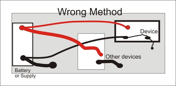
Let's look at why grounding to the battery post is rarely a good idea!
Here is a diagram of a typical system. The other loads on the system are represented by one box, and the device we are connecting is tied to the battery posts. This is typical for radio instructions, amplifier instructions, and MSD ignition system instructions. Note the "device", which could be an amplifier, MSD box, or any add on accessory, connects to the battery negative post or terminal:
This all looks good on the surface. We assume currents are like this:
We have 8.9 amperes on each device (R2) wire because we ignored the other ground paths in the shared grounds.
The problem is the device has other grounds on small wires that connect to the negative power buss. We really have this:
We have unwanted currents in our "device" small-signal grounds.
W1 8.95A
W2 7.16A
W3 1.79A
These unwanted currents are from ground loops. Ground loops are caused by improper wiring, where someone wrongly assumes ground is ground, and the battery negative post is a good ground or negative power source.
Any resistance from running the long ground lead to the battery negative, because it creates a ground loop with signal leads, shifts unwanted current into fragile, sensitive, signal leads.
It gets much worse though. If we fuse the negative and it opens, or if the battery or power source negative lead opens, we have this:
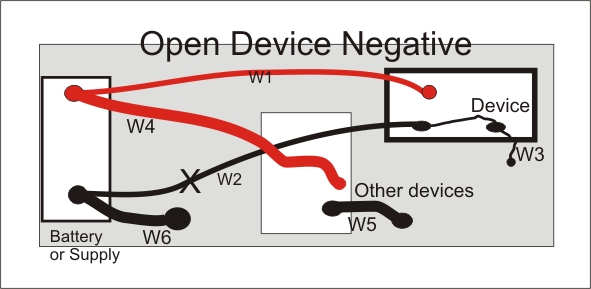
This results in the following circuit:
W1 8.118A
W2 0A
W3 8.118A
An open black-to-battery, either from an open fuse or a bad connection, will cause 8 amperes to flow through small signal leads. This can damage things or be a fire hazard.
While the above illustrates why we should never fuse a negative lead on a shared buss device, it gets even worse than that!!! What if we have this case, where a battery ground (W6) opens:
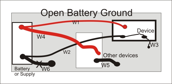
Now we have this:
W1 7.667A
W2 45.997A
W3 38.33A
This is devastating to almost any device, and is a major equipment or fire hazard. This is why some countries no longer allow fusing negative leads, or connecting negative accessory leads to battery posts.
The proper connection method is:
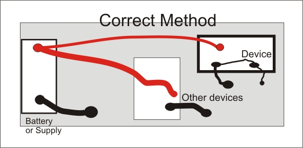
In a proper system, no add-on device in the system connects to the battery negative post, battery negative lead, or the ground stud for the negative lead. The battery negative post and battery negative leads connect ONLY to major grounds, which would normally be the engine block (very heavy lead for alternator and starter current) and to the vehicle chassis for all other devices! Any device that has a shared ground buss or a ground lead connected to exposed metal should NEVER be connected to the battery negative post or wire, and the device or equipment being powered should never have a negative fuse.
There is only one exception to this rule that will permit a safe negative fuse or negative to battery post connection. The only exception to the above rule occurs when the electrical device is completely ground isolated between the power ground and all signal grounds or any exposed enclosure or case metallic parts. Negative buss isolation will break any ground path other than the battery lead.
Spark Return
A final problem using ignition devices. We are all familiar with the outgoing path to the spark plugs, but we ignore the return path. The return path has just as much pulse current and energy as the "hot" path. The system will induce much less noise into unwanted places if the ignition coil grounds to the engine block, or to a cylinder head, with a short wide lead or the coil is mounted directly on the engine. Braiding is ideal for the external ground. This is another reason to use ground straps from the engine to chassis.
For the best EMI suppression, wide smooth conductors are much better than woven or stranded conductors. Unfortunately, solid wide conductors will break when flexed. Life when vibrated or flexed is more important than lowest impedance, so a shield lay braid is generally the best compromise between lowest impedance and the best mechanical characteristics.
Electrical Noise Electromagnetic interference (EMI)