Note: None of the problems below occur when the loop is on a band where the actual antenna is a full wave or larger.
The primary radiating area of a half wave loop is about 1/8th wavelength. We are
essentially end-loading a 1/8th wave long dipole when we use a 40 meter full
wave loop on 80 meters.
On 40 meters a full wave loop is like
end-loading two 1/4 wave long dipoles, so there is a full half-wave of total
radiating area and efficiency is high. Folding the antenna into a square kills
80-meter efficiency because the square is small, the sides out-of-phase, and so
only one side (the feedpoint side) radiates. One little mistake by adding a
small amount of resistance and efficiency falls into single digits.
In a recent QRZ thread, it became apparent some transmission line calculations in models are not accurate. This actually is true for many transmission line calculators, not just those in modeling programs. The poor transmission line loss calculators are reinforced by articles that contain bad measurements, like a 2009 article on ladder line loss.
Let's look at a few 40-meter horizontal loops with an open circuit loop as a reference, and compare it to others loaded by a 1/4 wave transmission line stub. We can also see how built-in transmission line calculators compare to a known good feed line loss calculator. One of the best calculators I've found is at VK1OD http://vk1od.net/calc/tl/tllc.php
What makes a smaller loop so difficult to tune correctly?
Radiation occurs from charge acceleration. This means we must have current flowing over linear (in line) spatial distance without something else nearby opposing that radiation with an opposing current. When a loop is full size, it has two areas that can freely couple to space:
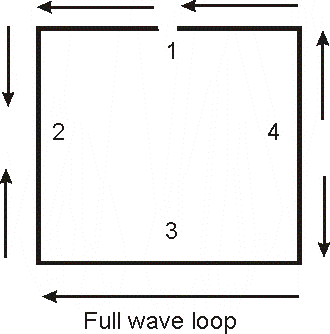
Section 1 is the feedpoint, and all areas of section 1 can radiate. Sections 2 and 4 have opposing currents inside each section, and with each other. They almost cannot radiate at all.
A full-wave loop looks like two 1/4 wave long dipoles fed in phase (currents support each other in radiating) while the sides suppress most radiation.
At half frequency, where the loop is 1/2 wave perimeter, all sides fight against each other. This means the antenna needs more current to radiate the same power, which also means radiation resistance has greatly decreased. The antenna needs much more current and more voltage to radiate.
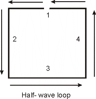
When we try to "load" this loop, we can only move the current maximum around. We cannot change the phase relationship. Without adding sections or protrusions that carry common mode currents, we can only change where the maximum and minimum of current and voltage occurs.
With no loads the loop is resonant, but current maximum is in the middle of the side diametrically opposite the feedpoint. Feedpoint resistance is terribly high, many thousands of ohms. If we only have a moderately high feedpoint resistance with a closed 1/2 wave loop, the antenna has high loss.
If we open the loop exactly opposite the feedpoint, the loop behaves like a bent dipole. There is very high voltage across the gap, and much higher than normal currents at the feedpoint.
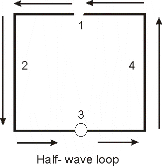
The feedpoint now has highest current and lowest voltage, making it a low impedance. Most radiation comes from the short area in wire 1, only 1/8th wavelength long. Sides 2 and 4 tend to cancel each other because they have the same currents flowing opposing directions. Side 3 has very little current and as such cannot usefully contribute to radiation.
We essentially have a 1/8th wave long dipole, and have no real way to make it better without extending the middle of sides 2 and 4 further apart without shortening sides 1 and 2! In other words to increase radiation resistance, the loop has to be made spatially larger.
If we have a loop like this with a high feedpoint resistance, over 10-20 ohms, the antenna has very high loss.
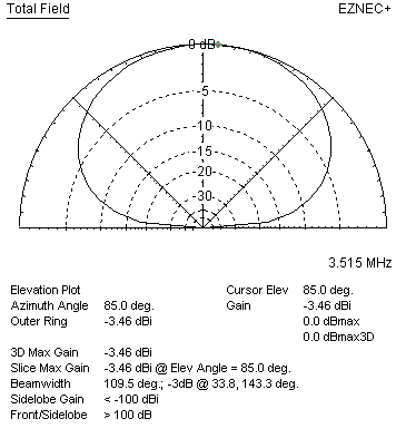
Reference loop, 40-meter full wave loop 36-feet high over medium soil, opened opposite feedpoint to make reasonable feed impedance on 80 meters. The problem with relay-switching the loop open is, with only 100 watts, relay contact voltage is 5000 volts peak. High voltage and high current is a direct result of having a small radiating area (folding the antenna in a square).
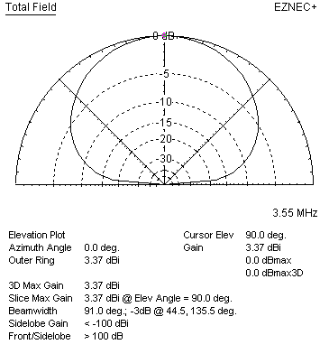
| EZNEC+ ver. 5.0 Horiz loop 10/12/2010 6:57:25 AM --------------- SOURCE DATA --------------- Frequency = 3.55 MHz Source 1 Voltage = 71.7 V at 81.97 deg. Current = 1 A at 0.0 deg. Impedance = 10.01 + J 71 ohms Power = 10.01 watts SWR (50 ohm system) = 15.197 (75 ohm system) = 14.267 Overall Efficiency 43.7% |
Stub decoupled loop (phosphor bronze) using real open wire line 3 inch spacing #18 AWG
stub is modeled as two parallel conductors
| EZNEC+ ver. 5.0 Horiz loop 10/12/2010 7:38:36 AM --------------- SOURCE DATA --------------- Frequency = 3.51 MHz Source 1 Voltage = 49.99 V at 0.57 deg. Current = 1 A at 0.0 deg. Impedance = 49.99 + J 0.4946 ohms Power = 49.99 watts SWR (50 ohm system) = 1.010 (75 ohm system) = 1.500 Overall Efficiency 8.6% |
(Efficiency a few percent higher using copper)
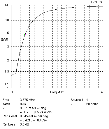
SWR plot of stub-switched loop. Resonant frequency 3.510 MHz
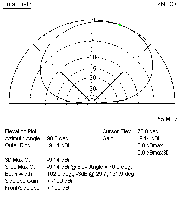
3.5 MHz using built in-transmission line loss calculator with values for Wireman 551 450-ohm line:

| EZNEC+ ver. 5.0 Horiz loop 10/11/2010 9:30:06 PM --------------- SOURCE DATA --------------- Frequency = 3.55 MHz Source 1 Voltage = 56.99 V at -9.09 deg. Current = 1.777 A at 0.0 deg. Impedance = 31.67 - J 5.07 ohms Power = 100 watts SWR (50 ohm system) = 1.605 (75 ohm system) = 2.381 Overall Efficiency 15% |
3.5 MHz Wireman 450-ohm ladder line using VK1OD calculator values inserted as a load:
| Parameters | |
| Transmission Line | Wireman 551 |
| Code | W551 |
| Data source | Wireman / N7WS |
| Frequency | 3.550 MHz |
| Length | 0.250 wl |
| Zload | 1.000e-7+j0.000e+0 Ω |
| Yload | 1.000e+7+j0.000e+0 S |
| Results | |
| Zo | 400.00-j1.63 Ω |
| Velocity Factor, VF -2 | 0.903, 1.227 |
| Length | 90.00 °, 0.250 λ, 19.056 m |
| Line Loss (matched) | 6.11e-2 dB |
| Line Loss | 74.492 dB |
| Efficiency | 0.00 % |
| Zin | 5.687e+4-j2.324e+2 Ω |
| EZNEC+ ver. 5.0 Horiz loop 10/11/2010 9:42:32 PM --------------- SOURCE DATA --------------- Frequency = 3.55 MHz Source 1 Voltage = 150.3 V at 16.42 deg. Current = 0.6938 A at 0.0 deg. Impedance = 207.8 + J 61.23 ohms Power = 100 watts SWR (50 ohm system) = 4.536 (75 ohm system) = 3.043 Overall Efficiency 2.2% |
There is 8.1 dB difference between the built in transmission line calculator and the external more accurate VK1OD calculator.
Look like not much problem on higher bands, except SWR bandwidth:
14 MHz with transmission line in EZnec
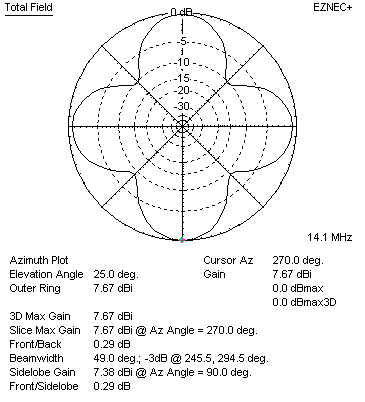
| EZNEC+ ver. 5.0 Horiz loop 10/11/2010 9:15:06 PM --------------- SOURCE DATA --------------- Frequency = 14.1 MHz Source 1 Voltage = 171.2 V at -1.4 deg. Current = 0.5842 A at 0.0 deg. Impedance = 293 - J 7.164 ohms Power = 100 watts SWR (50 ohm system) = 5.863 (75 ohm system) = 3.909 Antenna system efficiency 74.8% |
VK1OD RF Transmission Line Loss Calculator 14 MHz
| Parameters | |
| Transmission Line | Wireman 551 |
| Code | W551 |
| Data source | Wireman / N7WS |
| Frequency | 14.100 MHz |
| Length | 1.000 wl |
| Zload | 1.000e-7+j0.000e+0 Ω |
| Yload | 1.000e+7+j0.000e+0 S |
| Results | |
| Zo | 400.00-j0.78 Ω |
| Velocity Factor, VF -2 | 0.903, 1.227 |
| Length | 360.00 °, 1.000 λ, 19.191 m |
| Line Loss (matched) | 0.128 dB |
| Line Loss | 77.703 dB |
| Efficiency | 0.00 % |
| Zin | 5.89-j0.01 Ω |
| Yin | 0.169760+j0.000332 S |
| VSWR(50)in | 8.49 |
| Loss model source data frequency range | 50.000 MHz - 100.000 MHz |
| Correlation coefficient (r) | 1.000000 |
| Simulation using VK1OD calculator Horiz loop 10/11/2010 8:35:59 PM --------------- LOAD DATA --------------- Frequency = 14.1 MHz Load 1 Voltage = 3.405 V at -1.32 deg. Current = 0.5771 A at -1.32 deg. Impedance = 5.9 + J 0 ohms Power = 1.965 watts Total applied power = 100 watts Total load power = 1.965 watts Total load loss = 0.086 dB |