Top Page
How Torque Converters Work
The purpose of this page is to extend our insight
into how torque converters work, or what they do.
Torque converter "stall" or "slip"is based on the applied torque and the
differential RPM between the transmission input shaft and the engine.
Let's consider the zero MPH starting line point. This is the most simple point
to talk about. Gearing, weight, and speed are not a factor.
Even if we
know the shaft speed is zero, rendering weight, gearing and speed meaningless,
we still have to know the torque vs. RPM curve. Torque vs. RPM is also the same
as knowing horsepower and RPM. This is because horsepower, RPM, and torque are
all interlocked by the formula that tells us horsepower is (RPM*Torque)/ 5252.
If we know any two of the three that include horsepower, torque, or RPM, we
absolutely know the third.
If we do not know torque stall is specified
at or observed at, as well as the torque curve of our working engine, we cannot
possibly know the expected locked stall.
Let's look at an example.
The 10.5" Hughes converter in my car stalls at 2800 RPM with zero psi boost.
On a Superflow dyno, my engine has 180 lb/ft at 2800 RPM. 180 lb/ft is about 95
HP.
This converter stalls at 3900 with 8 psi boost, which is 395 lb/ft
and 293 HP.
The same converter stalls
at 4800 with 14 psi boost. This is 460 lb/ft and 420 HP. At this speed my torque
converter is multiplying torque approximately 2.3 times. My rear axle torque is
460*2.3*1.68*4.10 = 7287.5 lb/ft upon release of the transmission brake. Since
my tires are 28 inch diameter and the sidewalls "squat" 1.8 inches, the radius
to the track is 12.2 inches. The total forward thrust is 7287.5/(12.2/12) = 7168
lbs.
My car weighs 3200 lbs. If the tires had infinite traction and all
movement was forward acceleration would be 7168/3200 = 2.24G's. Most tracks will
never take that shock, so I have to leave much lower boost (and RPM) and "ramp"
into more torque. On a good track my car will peak around 2.5g in low gear just
after the suspension sets up. This results in a 1.15 or so 60 foot time, and a
ring gear life of about 150-200 passes.
This same
converter drops to 6800 on the shift at 28 psi. 28 psi at 6800 is around 1150 ft/lbs
or 1489 HP. This is where things get complicated. This drop not only depends on
engine torque, it is also dependent on transmission input shaft speed on the
shift. The rolling "stall", "flash", or "slip", whatever we want to call it, is
ultimately dependent on engine characteristics that determine engine torque vs.
RPM, car weight, gearing, tires, and speed.
This video
shows tire smoke on the 1-2 shift, where tire forward thrust briefly exceeds
traction limits from the torque surge.
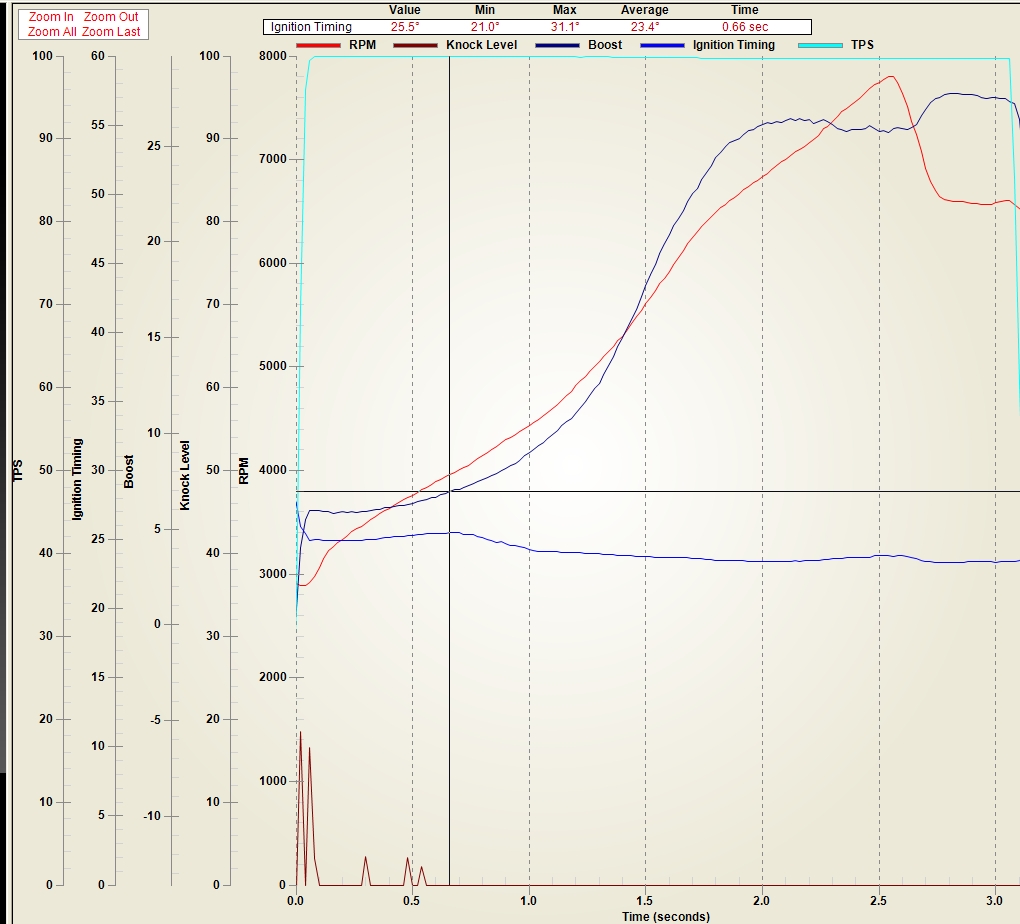
This screenshot shows torque
converter response through RPM, boost, and time data. TPS is throttle position.
Look at how RPM follows boost, and engine torque would also follow boost. The
crosshair position is where the car starts to roll out. Beyond that point
transmission input shaft speed is also a factor in RPM.
Torque Converter Physics
We can see that a torque converter is not just a slipping drive
that lets the engine stay at a high RPM. As strange as it seems to have to say
this, a torque converter also changes torque applied to the converter input to a new
torque value at the converter output! A more exact torque converter mechanical analogy would
be a slipping clutch followed by a variable ratio gear drive.
There are several web based papers on torque
converters.
MIT student paper
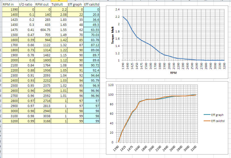
It contains this graph of efficiency, multiplication, and RPM:
I translated that with formulas derived from the following pdf file:
Turbo 440
transmission analysis
This is the resulting match between formulas I used and the
student graph:
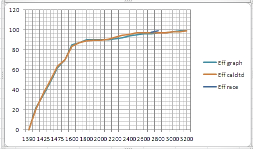
This is how efficiency overlays with data from a 5000-stall
8-inch race converter. I normalized the converter data to the RPM range of the
lower stall converter:
A plain language Wiki description is here:
Torque
converter non-engineering text
kennedys dyno tune
It's a Fluid Drive Clutch!
The "slipping clutch" allows the engine to move
around in RPM compared to the output RPM. This is why an automatic car can idle,
instantly move to high RPM even while the transmission input shaft is not
turning, or coast down with less engine RPM than a solid
mechanical lock would produce. There is a maximum differential in RPM (speed) for a given
amount of torque applied to the input, at a certain output shaft RPM range. This differential is commonly called the
"stall speed", because the engine "stalls" or is held at a certain RPM with a
certain peak torque. The actual "stall", however, varies all over the place with
applied torque and output (transmission) shaft speed. This is why a high stall converter, at very light throttle,
generally works perfectly fine on the street. On level ground and at modest
speeds, applied torque is so low the car often does not even behave like it has
a high stall converter.
Look at this video of a glide with high stall on
the street:
Alex LTD You Tube Glide
The variation in stall with load and output RPM is why different engines,
gears, and weights cause the optimum converter stall to move around. This gives
converter wizards a big recipe to sort through. The fluid slip is not much
different than a slipping clutch, except at some speed differential the fluid starts to lock harder.
It also heats fluid, and not an exposed steel surface or clutch disk, so the
power dissipated by the "fluid slip" doesn't "stink" as bad. The equivalent "clutch", because it is fluid driven,
eventually becomes nearly perfectly locked at a certain RPM. There is no torque
multiplication in a clutch or in a direct fluid couple. All either can do is
slip, and slipping will waste power by converting it to heat.
For a little brain exercise, try to think of a
device you can build that increases pressure or torque without a lever, or
without a gear working against another gear on a shaft or shafts. Like a teeter
totter, there has to be a fulcrum involved and some form of leverage.
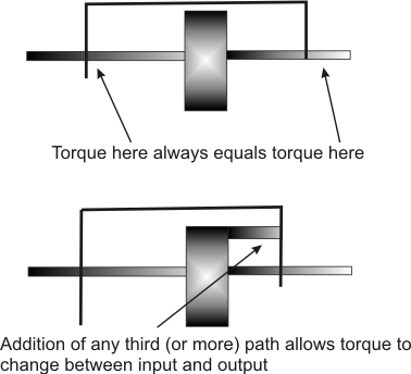
Torque is also a series function in a system.
Torque
is much like current in an electrical circuit. If a coupling device has one isolated path
with
nothing to divert torque, leverage against, or apply counter torque against,
torque is the same at both input and outlet. If we have anything between the engine and the
transmission, it cannot change torque unless it has a third mechanical path to
the transmission case or engine block. The torque out of the engine into the
device will always equal the torque to the transmission, absent any additional
path.
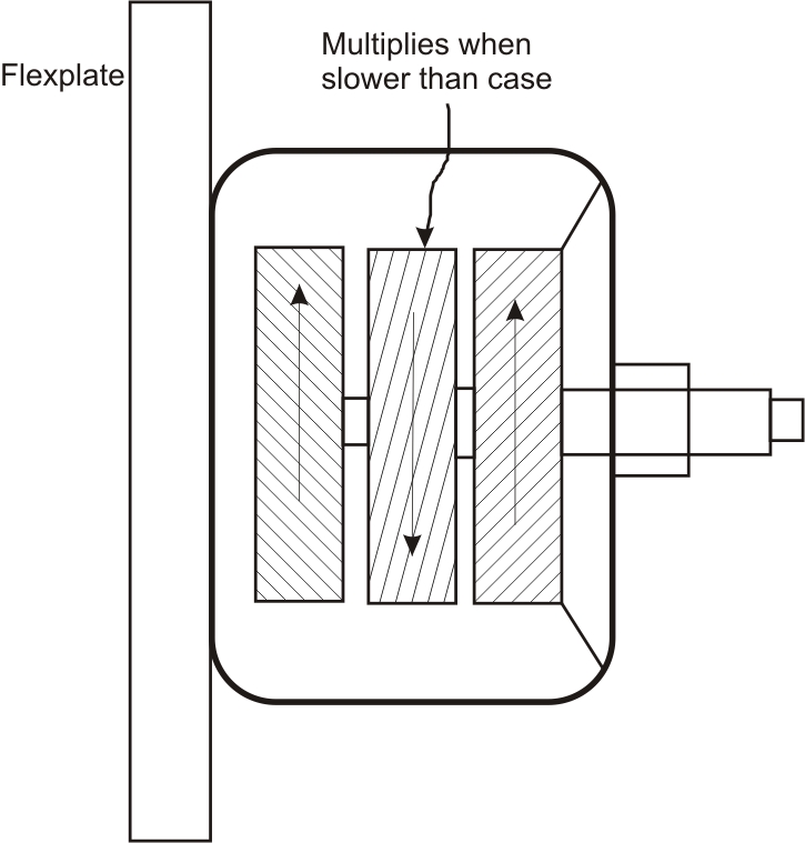
It's Also a Fluid Gear!
The second most important thing a torque
converter does is commonly overlooked. This is ironic to me, since a torque
converter is actually named after this function. A torque converter contains the
hydraulic equivalent of a variable-ratio mechanical gear.
This effect is created by the addition of a stator and one-way
clutch to a conventional 1:1 ratio fluid drive. The one-way clutch is anchored
to the transmission, and becomes the necessary third path for leverage. The impeller spins, directing the fluid in a stream through a stator and
into a turbine. The fluid is redirected out of the turbine, and eventually back into the
impeller. This means the fluid has to pass through a stator at least once, which is only a
true stator when locked.
The stator is locked by a one-way clutch system when the
output shaft and input drive (the converter case) are operating at large
rotational speed differential. The stator blade angle
forces the fluid stream to be redirected at a sharp angle into the turbine
blades. The fluid pressure also turns the stator in anti-rotation against the
transmission case. This puts pressure against the transmission case opposite to
the output rotation, just like a gear does on the shaft supporting the gear. This angular change
and pressure against the transmission case produces much higher output pressure, but decreases velocity
by the same ratio pressure increases. This system is the fluid driven analogy of a lever, a gear set, or any other
mechanical speed-to-torque conversion. Like any lever or gear, the fluid
redirection trades movement distance (rotational speed) for increased pressure (torque). Maximum gearing is at
stall, where some large converters with narrow RPM ranges and/or multiple stages can have 5:1
torque multiplication. Most automotive converters are generally said to produce
about 2:1 torque ratio, while some
finely tuned converters claim 2.5:1 (or higher) torque multiplication.
Again, this torque multiplication is not much different than
what would be expected using a
mechanical gear set driven by a fluid clutch, with the exception it has a
variable rate that is inverse to rotation rate differences at input and output. As converter output
shaft RPM increases, the center stator unlocks and
starts to rotate. This reduces the fluid's redirection, removing the countering
pressure from the transmission case and reducing the redirection and pressure of
fluid. This causes the turbine's velocity
(speed) to increase while the turbine's pressure (torque) decreases. Thus we
have a hydraulically-coupled version of variable gear ratio.
The efficiency relates to power
loss, so we have to deal with horsepower. Horsepower is (RPM*torque) / 5252.
This is a spread sheet using standard math, with data extracted from a typical
converter design found on Internet. Here is an efficiency chart:
Looking at the spreadsheet, which is based off
real converter data, we see as the stator eventually assumes the speed of the
input drive, fluid redirection is minimal. When the stator, impeller, and
turbine assume the same speed, the converter comes very close to
a 1:1 ratio with no torque multiplication. There is only some small amount of fluid slippage,
which causes a small
RPM loss. This RPM loss represents a small horsepower loss. If it is 5% slippage, the
system loses around 5% power as heat.
Since the spreadsheet above starts at zero
transmission input RPM, it represents low gear performance. If we had a low gear transmission ratio of 1.80,
and we shifted to 1:1 at 7500 RPM, the
transmission input shaft will abruptly change from 7420 RPM to 4122 RPM. (7420/1.80 = 4122 RPM).
When that happens, the TC output speed moves to 4122 RPM.
The load on the engine quickly causes the engine to readjust to the RPM required
to hold the output at 4122 RPM. We now have the engine back just below
6000 RPM. Throughout high gear, the spreadsheet looks like this:
High gear starts as a 1.21 ratio gear set would
behave, and moves to a 1:1 final drive. Our two-speed transmission behaves like
it has the following ratios going down the track:
This is why automatics feel "smooth", but have fast ET's.