Wiring
This is how I am wiring my HO model train system. It will eventually include switching systems for turnouts, power control wiring, railroad signal lights, and train and railroad car and engine block detection.
Box colors indicate tracer color of main cables, clear boxes are open wires in twisted pairs
Colors inside boxes are wire colors in each cable. I always start at the lowest number or priority, or the outside or left point, and number by increasing color.
| 0 | Black | Bk or Blk |
| 1 | Brown | Bn, Br, or Brn |
| 2 | Red | R or RD |
| 3 | Orange | O, Or, or Org |
| 4 | Yellow | Y, YL, or Yel |
| 5 | Green | Gn or Grn |
| 6 | Blue | BL, Bu or Blu |
| 7 | Violet | Vi, Vio, or V |
| 8 | Gray | Gy or Gry |
| 9 | White | W, Wh, or Wht |
I've now decided to number things by the layout block. There are seven blocks so far. This way if I add a block I won't need to redo all my papers. The old things stay the same.
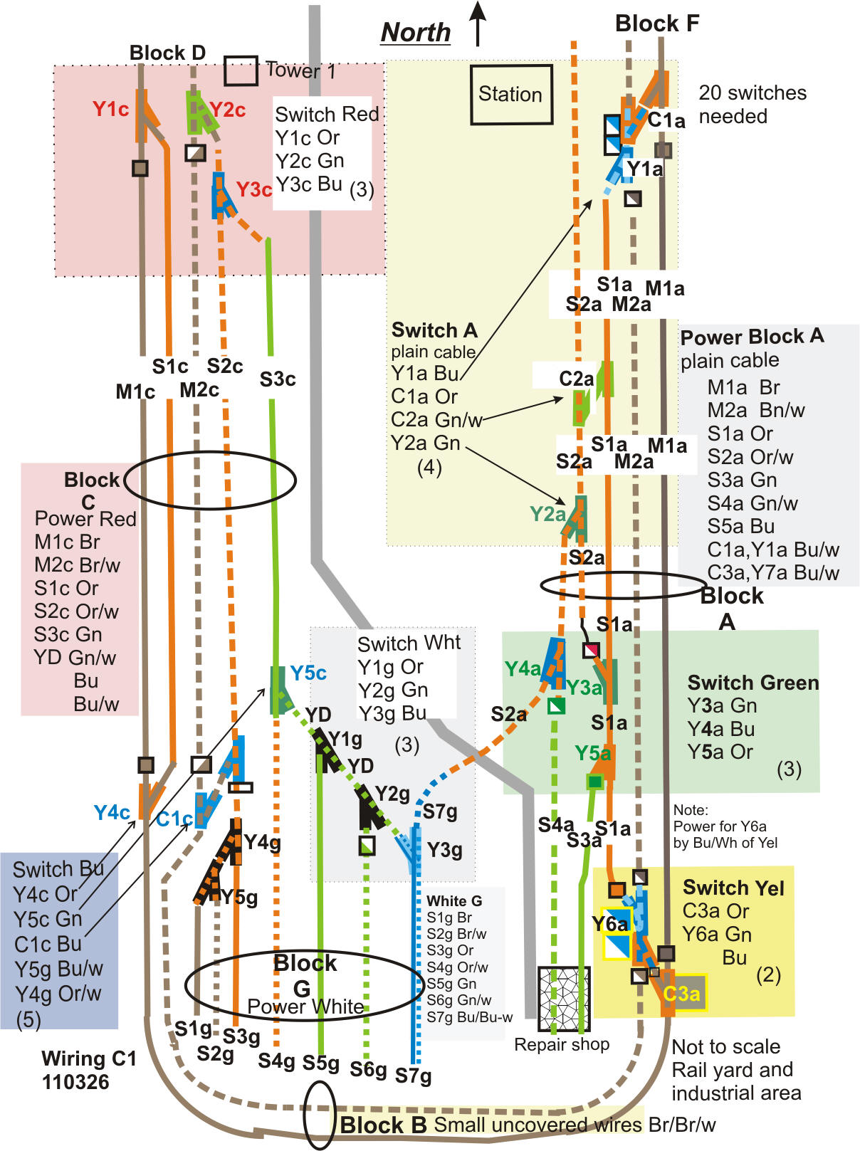
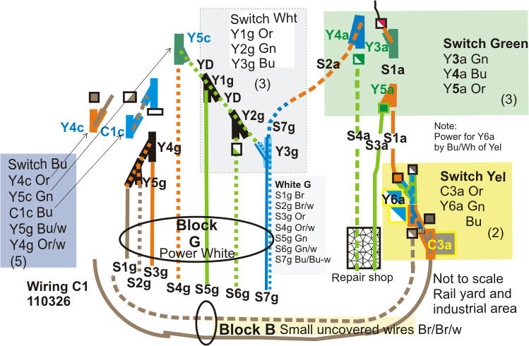
This diagram shows turnout (switch) wire codes in the yard area. There are around 22 or 23 electronically controlled turnouts (so far). Manual turnouts or fake turnouts not included.
Main lines and spurs/sidings get Y numbers. Crossovers get a C number.
This is the actual area shown above. It is about 20 feet deep.
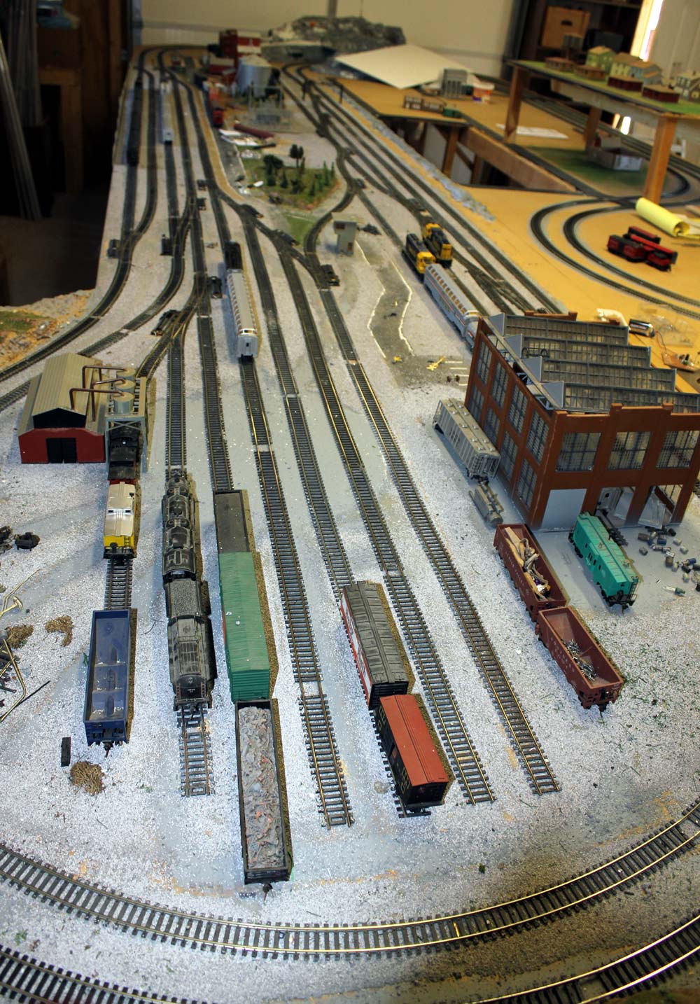
My agricultural and rural residential area is in the sections that lift out. They unplug and can sit on their own legs to allow better access to the layout center.
Track layout, for now, is finished.
Base coats are all that is complete at this time. The real landscaping will start as wiring and signals are completed
New logic panel. The panel below controls this layout.
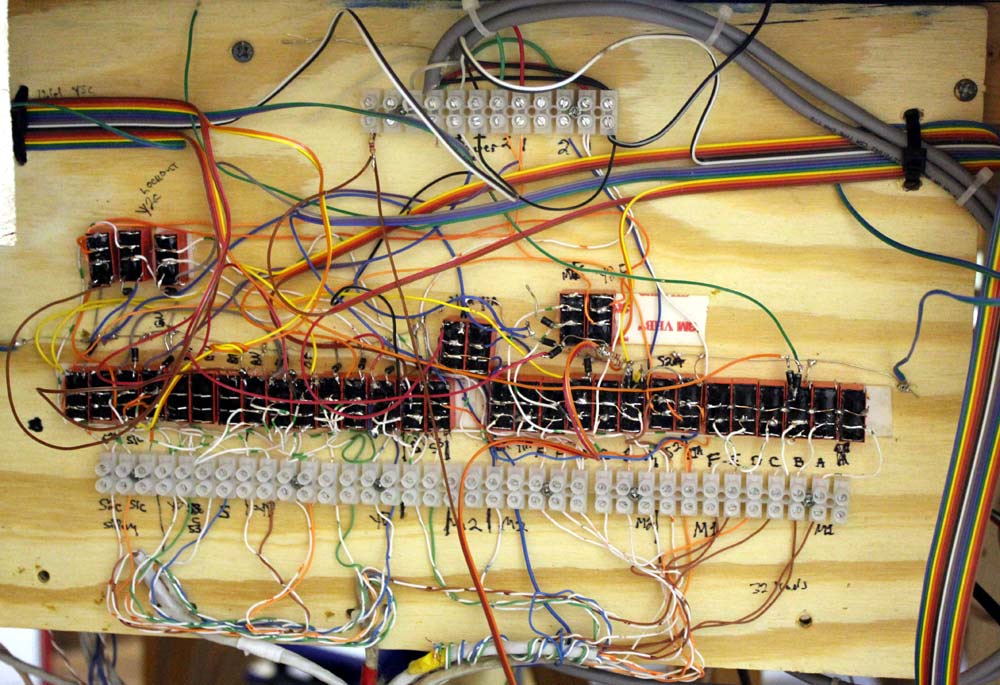
This is old technology diode and relay logic. This is because I am using DC, and not DCC (yet).
It took about 5-10 hours to do the logic. I really enjoyed thinking through the problems. I know dead-bug haywire looks bad, but the diode-relay logic does everything I want to do.
What this does is:
When a siding or spur is not selected, nothing moves on it.
When a siding is selected on one end, things can only move away from the open termination. A locomotive cannot be driven into an open switch port.
When a path is selected to an outside mainline track, the control for that outside track is in effect all the way into the deepest path of the path.
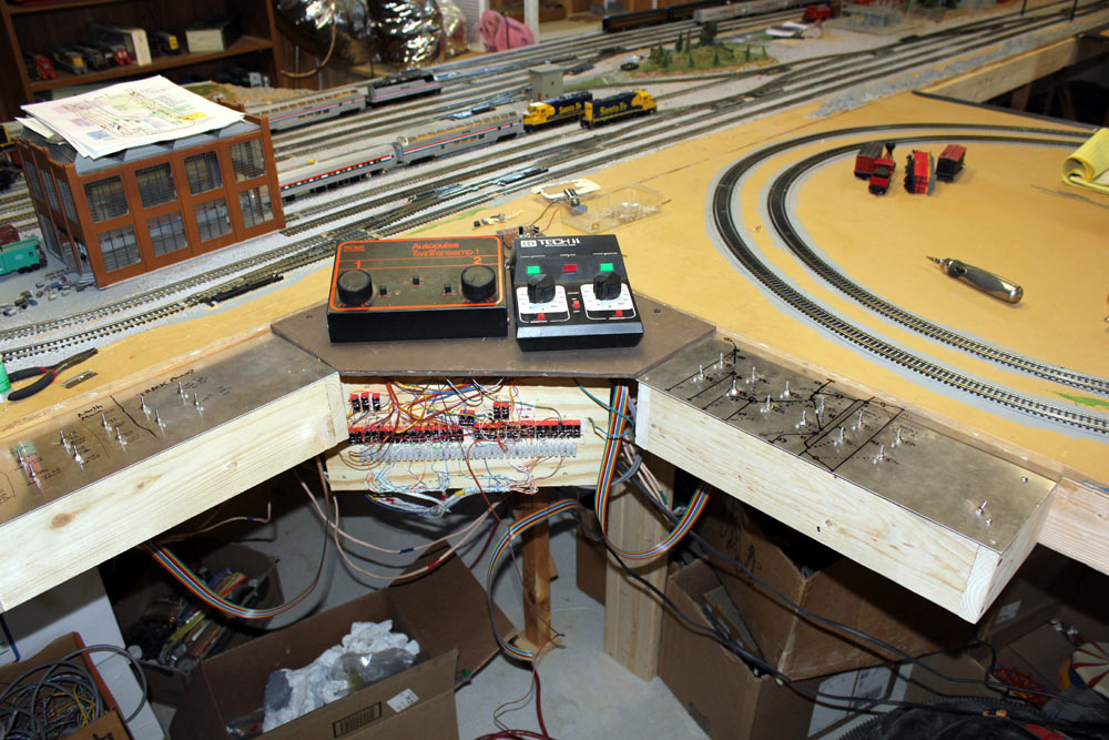
When the outside main lines are not connected through a path into center rails, a secondary controller comes on line. This lets me move things around in the center while the mainlines are running. This way I can prepare a train while mainlines are running. East half of the yard is control 1, and west half is control 2. Controls can be manually blocked also. The "Wye" (S7g) is the logical divider for halves.
For example if I route a train into the Wye from M2, the control for M2 has full authority until S7g is reached. At that point throwing Y3G connects S7g to whatever the destination track is. If it is M2 again but going in the opposite direction, nothing else needs changed. One single toggle switch flip gets the locomotive out of the Wye back to M2.
The same is true if I use a cross-over to move a train across M2 into the center area. The controller for M1 has full authority across the entire trip, while M2 is shut off in any blocks approaching the cross-over at any unselected port. This prevents a train from accidentally slamming into a crossing train or derailing.
My New Control Center
My IR detector and track disconnect circuit board:
My turn out control board:
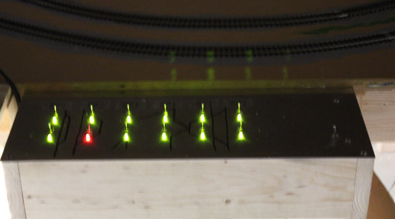
The board below doubles as a track power control board, plus it can run some signals!
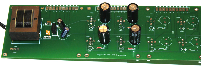
One board has power supply and can control up to 12 turnouts. Output is a pulse. The LED's light red (orange) or green depending on direction, and it provides a positive or negative DC output that indicates position.
It is instantly resetting. Switches can be rapidly clicked back and forth and the track will follow.
One power supply can power almost limitless turnouts, additional sections are easy to add. I current have one power section running 24 toggles and 20 turnouts, some of which are double turnouts that work from one control!!
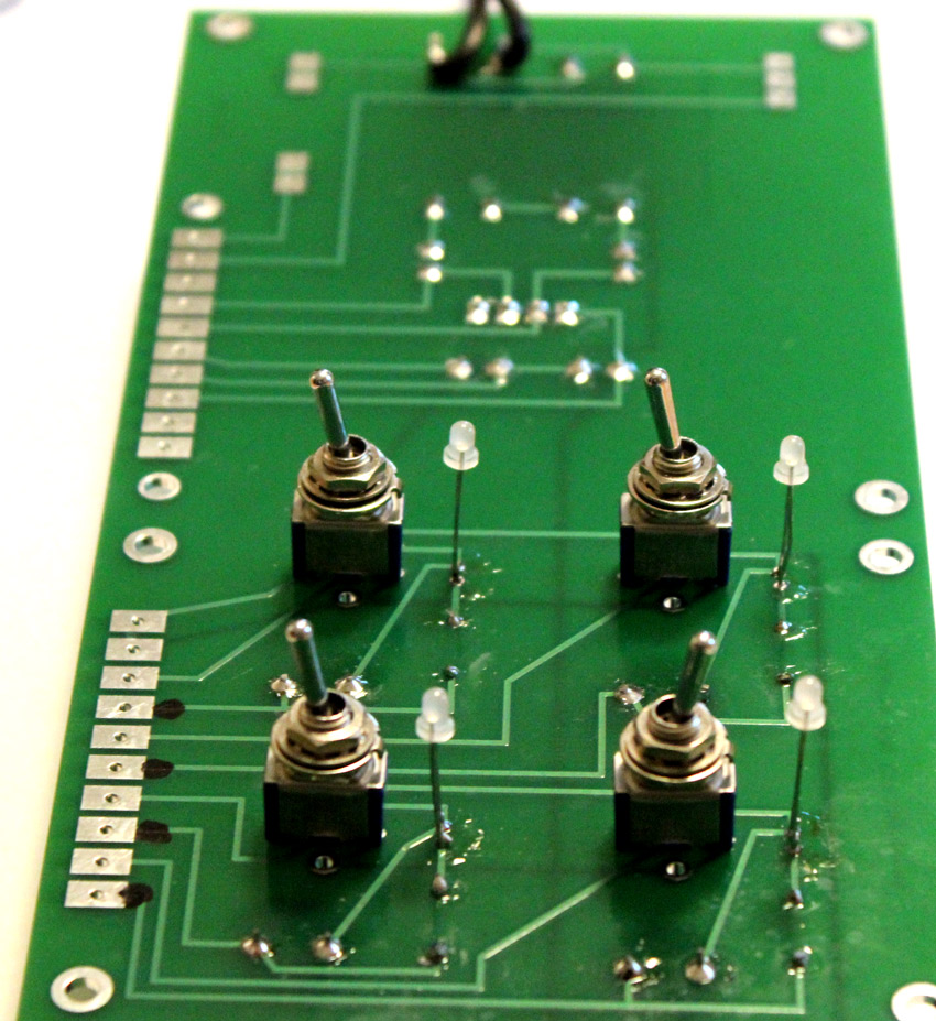
Next to each toggle is an indicator LED, showing green for normal or red for thrown. Either direction can be set as normal.
There is also a steady output of 12 volts positive for normal and 12 volts negative for thrown.
At work. Powering 12 turnouts. Works flawlessly.
Note these are BASIC circuits, and not necessarily the final circuitry.
This is my basic turnout control wiring. It has the following features:
1.) Momentary power to turnout motor, but reliable hard movement.
2.) Remembers position
3.) Inexpensive
4.) Two wires to turnout when D1 D2 diodes are at turnout
5.) DL1 and 2 can be track signals. As many signals as needed. One additional wire to switch will add two indicator lamps. lamps can be LED's or a bi-color LED with the addition of a current limiting resistor (just like more of R1 and D3 and 4).
6.) Instant reset time for next throw. No waiting.
My IR detector. This detector, with the correct IR LED, will detect a train within a 4-foot long block.
It has either open collector high current output, or sources enough current to light an external LED.
Signal light logic to interface with track control circuits
J2 open, DL2 lights
J2 shorted, DL1 lights
 +
+
This circuit automatically reverses the wiring at a Y.
It goes to the Blue and Blue-white wires at S7g in the following layout:
For comments please contact me at (type it in!!):

copyright 2011