Building a CW (and possibly AM) transmitter at this link, I decided to use a choke input supply. Had I used custom components, my first choice would have been a good capacitor input supply.
Being a typical "cheap ham", my decision to use a choke was based on using readily available salvaged power transformers. My collection of power transformers are largely pulled from old equipment I've scrapped. Like many of us, my home project transformers are usually not specially ordered for a particular project. My transformers were mostly harvested from old gear with vacuum tube rectifiers.
Apparent and Normal Power Factor
You probably never heard of this or considered it, but power factor causes some very strange effects in a power supply. Regular power factor is where the current and voltage are not in phase, and so the current times voltage no longer tells us the real power of the system. This is reactive power, and can even be called "VAR power" or volt-amperes reactive power. A transformer with significant flux leakage or that has a secondary loaded with an inductive or capacitive load has phase shift between voltage and current. This causes the primary to appear reactive and not resistive. This increases heating in components for a given amount of real power load.
Capacitor input supplies, or supplies with inadequate filter choke inductance, have a different problem. They draw significant current only over a small portion of the AC cycle. This causes the peak to average current to spread further apart, and this can greatly increase heating and losses because of I^2R losses in conductors and components. These systems are also known as non-linear loads.
The high peak current and low average current loading, or non linear load, is why we cannot measure line voltage to determine line voltage regulation with a large capacitor input supply. This is why normal wiring voltage-drop tables or resistance calculations do not apply with high power capacitor input supplies, like modern kilowatt-level RF amplifiers.
You can read about power factor and non-linear loads at this external link.
Transformers used in vacuum tube rectification systems almost always have higher primary and secondary resistances than transformers used with solid state rectifier systems. There is a good reason for this. Vacuum tube rectifiers are much "softer" on the secondary than solid state rectifiers. With their high plate resistance, high vacuum rectifiers pull current over a fairly significant fraction of the sine wave. This results in fairly lower harmonic levels, and a bit less apparent power factor. The softer waveform reduces transformer stress for a given load power.
Some equipment also uses choke input supplies. An input choke reduces the peak current by increasing the time current is drawn from the transformer. This reduces apparent power factor and stresses even further than the already "soft" rectification of a high vacuum rectifier.
Capacitor input supplies, especially those using solid state rectifiers and low ESR (equivalent secondary resistance) transformers, operate with very high apparent power factor. Current is drawn only during brief periods near AC waveform peaks, when transformer voltage exceeds the voltage stored in the filter capacitor at the output of the rectifiers. This makes the peak current very high compared to average current. The heavy peak loading squares off the sine wave, and harmonics are produced. The waveform is no longer a sine wave, the ratio of peak current to average current is very high, so we cannot use the more traditional displacement power factor. Displacement power factor applies to reactive loads that shift or "displace" the relationship of current and voltage, not to loads that distort waveform shape or load the line only at voltage crests.
The rectifier side of a power supply system, the area before filtering takes place, has a varying waveform that almost always is not sine-shaped. This means it contains harmonics. Standard RMS conversions or averaging of current levels cannot be applied through Ohm's law to determine component heating. Unless the filtering sections have a large filter choke, current generally has high peaks with shorter than normal duration. Most of the load energy is extracted from the transformer over a very short period of time. High-peak short-duration current waveforms greatly increase loss (meaning more heat) in any resistance. The standard P = I²R formula, when using dc load or average current, no longer applies!
Let's assume we have a typical 1-amp load capacitor-input supply that is power from a high-quality low-resistance power source. If we add a 30-ohm resistance on the AC side of the filter capacitance, we might assume the heat would be 30 watts, based on P = I²R. We might expect, since 1²*30 = 30, that resistor heat would be 30 watts. In fact a high quality source in a fairly stiff supply with a series 30-ohm resistor someplace the AC side of the filter capacitor could easily produce 60 or more watts of heat in the 30 ohm resistor with an average load current of only 1 ampere.
This all raises an important point. We sometimes hear claims that replacing a vacuum tube rectifier with silicon rectifiers extends transformer life of "marginally sized transformers". This idea is often based on reduced filament load significantly reducing transformer heating because "10 watts of transformer load is removed". This is generally not the case! Removing 5 volts at 2 amps actually has the following effect on the transformer:
Most energy passes through a traditional power transformer, with only a small percentage of energy turned to heat. High apparent power factor loads, like the load produced by a capacitor input filter system, produce a great deal more heat in the transformer than resistive loads. We don't save as much heat as we thing by removing a low power resistive load, while higher power loads exist, especially the HV secondary load with a high apparent power factor.
Transformer heat caused by the filament load is a little less than the filament current times the difference between no-load and full load rectifier filament winding voltage. Let's say removing a 5U4 rectifier results in filament winding voltage increasing from 5 to 5.4 volts. The voltage drop in this case is 0.4 volts, and current is 2 amperes. Replacing the 5U4 with a silicon rectifier removes some amount less than 0.4*2 = .8 watts of heat. Convection and radiant heat might contribute another one watt maximum of heat applied externally to the transformer, so we save somewhat less than 2 watts of heat (counting the radiant heat) in a component already dissipating 10-30 watts. Much of that radiant heat would be added back in with any additional dropping resistors or with higher dissipation in other components from increased high voltage.
The real problem is a solid state rectifier has a very sharp transition into and out of conduction....as well as a very low on resistance. This greatly increases PFa (the apparent power factor) of the HV secondary and primary windings. Since the solid state rectifier has a harder turn-on and much lower "on" resistance than a tube, power factor increases on a much higher load power winding. This more than offsets the savings in heat produced by removing the rectifier filament's resistive load.
Heating generally is reduced only in choke input supplies, because the addition of semiconductor rectifiers won't change power factor much in a choke input supply. Transformer heating can actually increase when high vacuum rectifier tubes are swapped to solid state in a capacitor input supply, because the apparent power factor becomes worse.
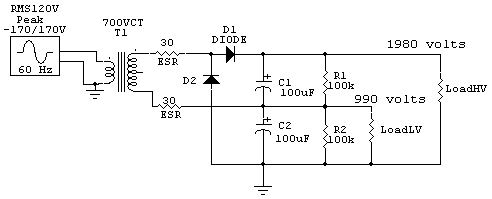
There are several ways to alter voltage from a transformer. ESR resistors in the drawings below represent transformer ESR.
Let's consider a typical 700-volt center tapped winding:
Voltage Doublers

This system produces a dc output voltage around 2.8 times secondary RMS voltage. This system will produce around 1980 volts dc no load. This more than doubles secondary winding heating for a given load power because peak current is increased. The secondary has dc voltage superimposed on it with common doubler schemes, increasing chances of insulation failure. The voltage doubler also provides half voltage, or 990 volts dc, but it is only suitable for light loads because the 900 volt point is only halfwave rectification. Transformer heating due to ESR represented by the two 30-ohm resistors.
A voltage doubler like this also places transformer secondary insulation under stress, with 2200 volts peak voltage between windings and 2000 volts to ground possible.
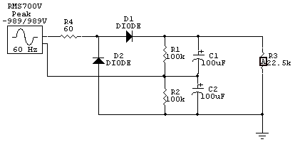
This is a spice model of a 700V RMS transformer doubler circuit. Load is 150 watts. R4 represents transformer ESR, and so the dissipation in R4 will be the transformer heat.
High voltage load current is 81.45 mA. Many people think heat in R4 is simply I^2*R, but that is not true. With a capacitor input supply there is an apparent power factor that makes heating more than expected. In this case, with a 81.45mA 150 watt load, we might assume heating is 0.4 watts in R4 (the transformer). In fact the average transformer heat is almost 10 watts. This is because RMS current in R4 (transformer loses), appearing in short pulses, is about 400 mA RMS!
Output voltage is 1.833 kV.
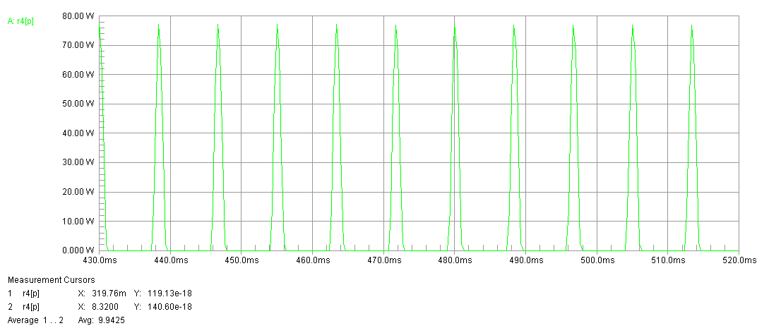
Transformer current in voltage doubler results in pulses of heat that are very large.
This would also be the waveform of transformer current.
Under revision.....
Bridge Supply
We can use a full wave bridge across the entire secondary with a capacitor input supply. Supply dc voltage is about 1.4 times RMS voltage. Power factor is not greatly increased, so heating is proportionally about the same for the same load power as a grounded center tap system. This system will produce around 1000 volts dc. As a bonus, the center tap can provide 500 volts dc if filtered as shown! No additional components are required, and the center tap voltage is full wave rectified.
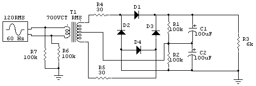
In this case with 150 watts into the load, heating in R4 and R5, the combination representing the same 60 ohm secondary ESR, is 8.46 watts total. We have saved a little heat with the same load power and the same transformer by going from a doubler to a full wave bridge.
This tells us the idea we can get twice the power from a given transformer by going to a doubler is wrong. We really should run, for the same heat, about 80% of the power. What it means is we can't get extra power from a given transformer by using a doubler, we actually get a little less.
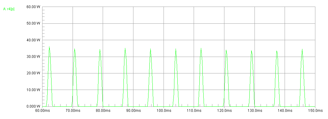
This is the half-power of the transformer in the bridge. This is the power in R4. Total heat is represented by the total power in both R4 and R5.
This would also be the waveform of the transformer current.
The repetitious peak transformer secondary current is 1.52 amperes to deliver 158 mA to the load. This is about a 10:1 ratio of peak to average current.
Full Wave Bridge with Choke
We can use a full wave bridge across the entire secondary with a choke input supply. Supply dc voltage is about 0.9 times applied RMS voltage with enough filter choke reactance. Power factor is greatly reduced, so heating is proportionally much less for the same load power as a capacitor input system. This system will produce around 900 volts dc for load currents greater than critical value. If the filter choke is place on the grounded side of the bridge rectifier, or a second choke is used there, dc voltage is reduced at the center tap. A properly designed supply could produce 900 and 450 volts. Power factor is low, reducing transformer heating for a given load power.
We can use a grounded center tap full wave rectifier with a capacitor input filter. This system produces around 1.4 times the center tap to outer lead RMS voltage at the load. The 1000 VCT transformer will produce around 700 volts with light loads.
We can use a full-wave grounded center tap rectifier system with a choke input filter system. Supply dc voltage is about 0.9 times the half-winding RMS voltage with enough filter choke reactance. Power factor is greatly reduced, so heating is proportionally much less for the same load power as a capacitor input system. This system will produce around 450 volts dc for load currents greater than critical value. Power factor is low, reducing transformer heating for a given load power.
With this single 1000-V CT transformer using different common rectifier and filter systems, we have a choice of 2800, 1400, 900, 700, or 450 volts.
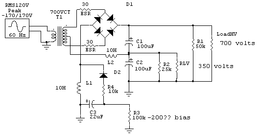
This supply moves the choke into the negative rectifier lead so I can extract bias from the AC voltage appearing across the choke. I've done this in a Globe Scout and it works OK.
This is a full wave bridge that uses the transformer center tap to obtain half voltage for the low level stages and screen grids of the PA tube. R1 is the HV load, R2 the low voltage load, and R3 the bias system.
Diodes are conventional 1N4007's in a typical supply.
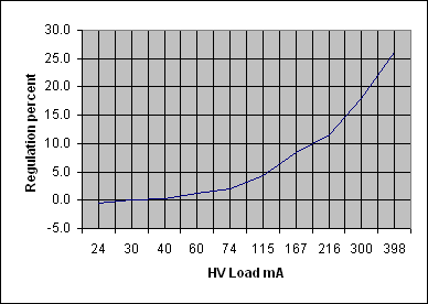
| 120 Vac Line | Extra choke, 50K bleeder HV, Resonant choke | |||||||
| Load Ohms | Load Power | Load Ma | HV | LV | ESR | ERS2 | ESR3 | Sag % |
| 50000 | 8 | 12 | 617 | 325 | ||||
| 25000 | 15 | 24 | 605 | 307 | 1012 | -0.5 | ||
| 20000 | 18 | 30 | 602 | 317 | 508 | 0.0 | ||
| 15000 | 24 | 40 | 601 | 319 | 100 | 252 | 0.2 | |
| 10000 | 35 | 60 | 595 | 313 | 309 | 238 | 283 | 1.2 |
| 8000 | 44 | 74 | 590 | 301 | 351 | 327 | 275 | 2.0 |
| 5000 | 67 | 115 | 577 | 280 | 312 | 322 | 319 | 4.3 |
| 3333 | 92 | 167 | 555 | 262 | 430 | 377 | 374 | 8.5 |
| 2500 | 117 | 216 | 540 | 255 | 303 | 368 | 351 | 11.5 |
| 1700 | 153 | 300 | 510 | 249 | 357 | 337 | 363 | 18.0 |
| 1200 | 190 | 398 | 477 | 240 | 338 | 347 | 338 | 26.2 |

