Bias and Sequenced Grid Block CW Keying (soon)
Bias and Grid Block Keying
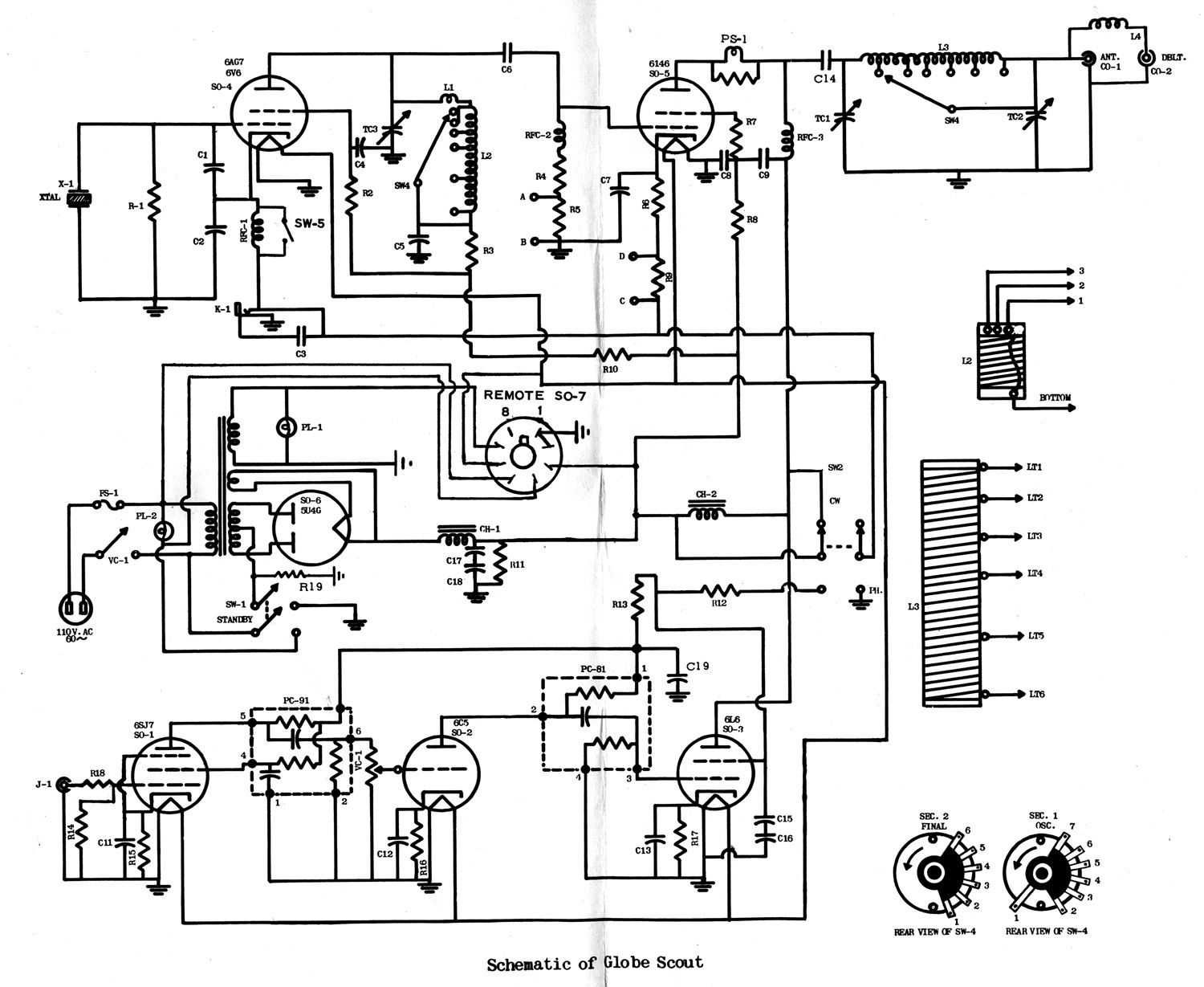
The power transformer in the Globe Scout is a major limitation. The transformer only has one high voltage winding. This means all lower voltages, such as supply voltages for low level speech and RF stages, are derived from the 500 volt high voltage source with dropping resistors. This is a good strong transformer, it just lacks the HV winding taps to be an ideal transformer for all the required voltages.
The power transformer voltage is 600 Vac. Normally a choke input supply gives about .9 times RMS voltage minus rectifier drop, or about 500 volts.
Bleeder resistance is too high to hold the filter output voltage at normal choke input voltage of 500V, so unloaded voltage soars a bit higher.
Worse yet, all stages run from dropping resistors, so all the low voltage tubes and screen grid of the 6146 go to 500 volts or more when the key is up!
I found a novel way to correct this while supplying negative voltage for grid bias. I moved filter choke CH-1 into the center tap of the power transformer on the ground side of SW-1, and rectified the AC appearing across the filter choke to provide a negative DC supply.
I moved the 6146 screen feed from the junction of CH-1 and CH-2 to the bottom of the plate choke RFC-3, on the lead common to the 6L6 plate.
The 6AG7/6F6/6V6 oscillator and audio stages operate from a much stiffer voltage divider and the center of the two electrolytics, which now tie into the center tap of the bleeder/voltage divider. This eliminates low voltage soaring while the key is up.
Even if you do not change to grid block keying, adding this circuit and biasing the 6146 grid negative will improve output power and reduce open key voltage on the CW jack. This modification will allow moving the 450-ohm bias resistor from the 6146 cathode into the modulator plate circuit.
Tank Circuit
The tank circuit in the Globe Scout series does not work very well on lower bands as built. The 365 pF loading capacitor is much too small for lower bands, but it can easily be fixed without tearing up the rig. An easy patch without destroying the rig is to solder a 160pF or 220pF 1000V mica capacitor across the loading capacitor. Make up a 680 pF 1000V capacitor in a PL-259 connector also.
When working 40 and higher, use the standard RF output port.
When working 80 or 75, use the "doublet" port.
When you work 160 meters, use the doublet port with the 680pF screwed into the empty regular RF output port.
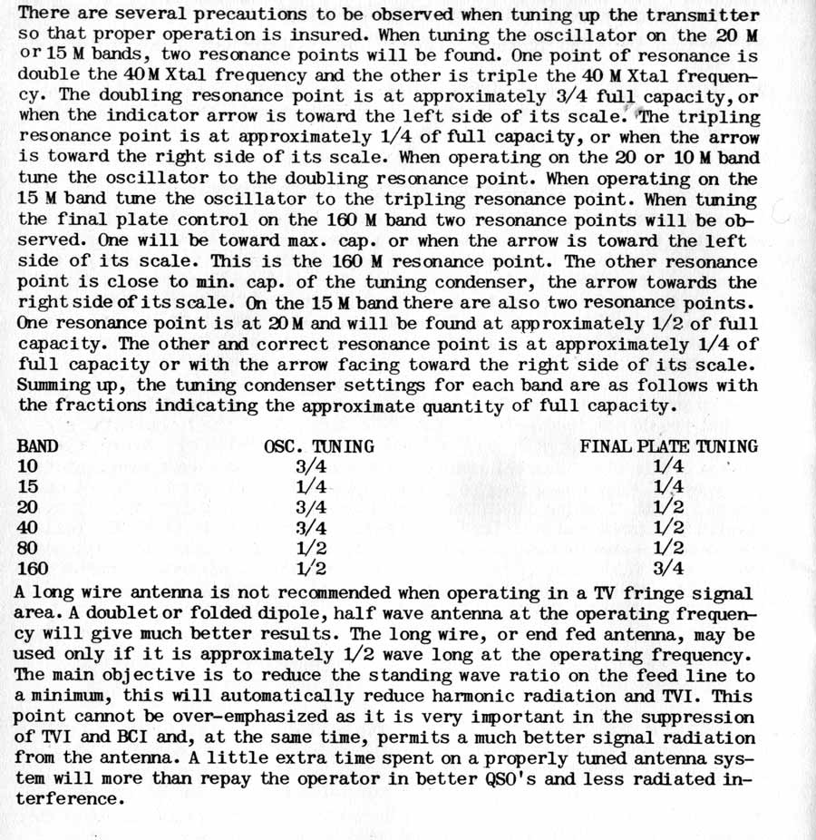
WRL tuning instructions:
Correction For Oscillator Pulling
Remove the ground from the driver tuning capacitor from the crystal socket. The original ground point puts buffer RF plate current from the "OSC TUNE" capacitor back into the crystal.
Route the tuning capacitor ground ground wire (bare buss wire at ground lug of osc capacitor) to the terminal strip ground where the driver bypass capacitor is grounded. This is only a partial cure, but it is much better than doing nothing about pulling.
Audio System Modifications
Original Circuits
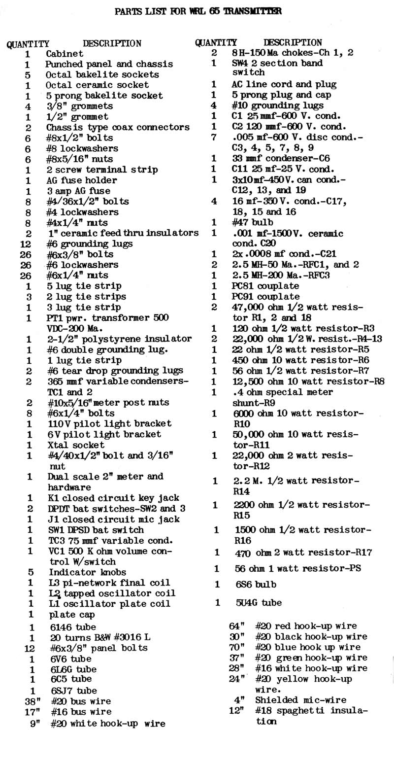
Meter shunt is R9, 0.4 ohms
since 2004/09/27