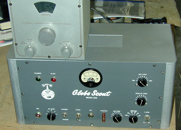
Globe Scout 65A
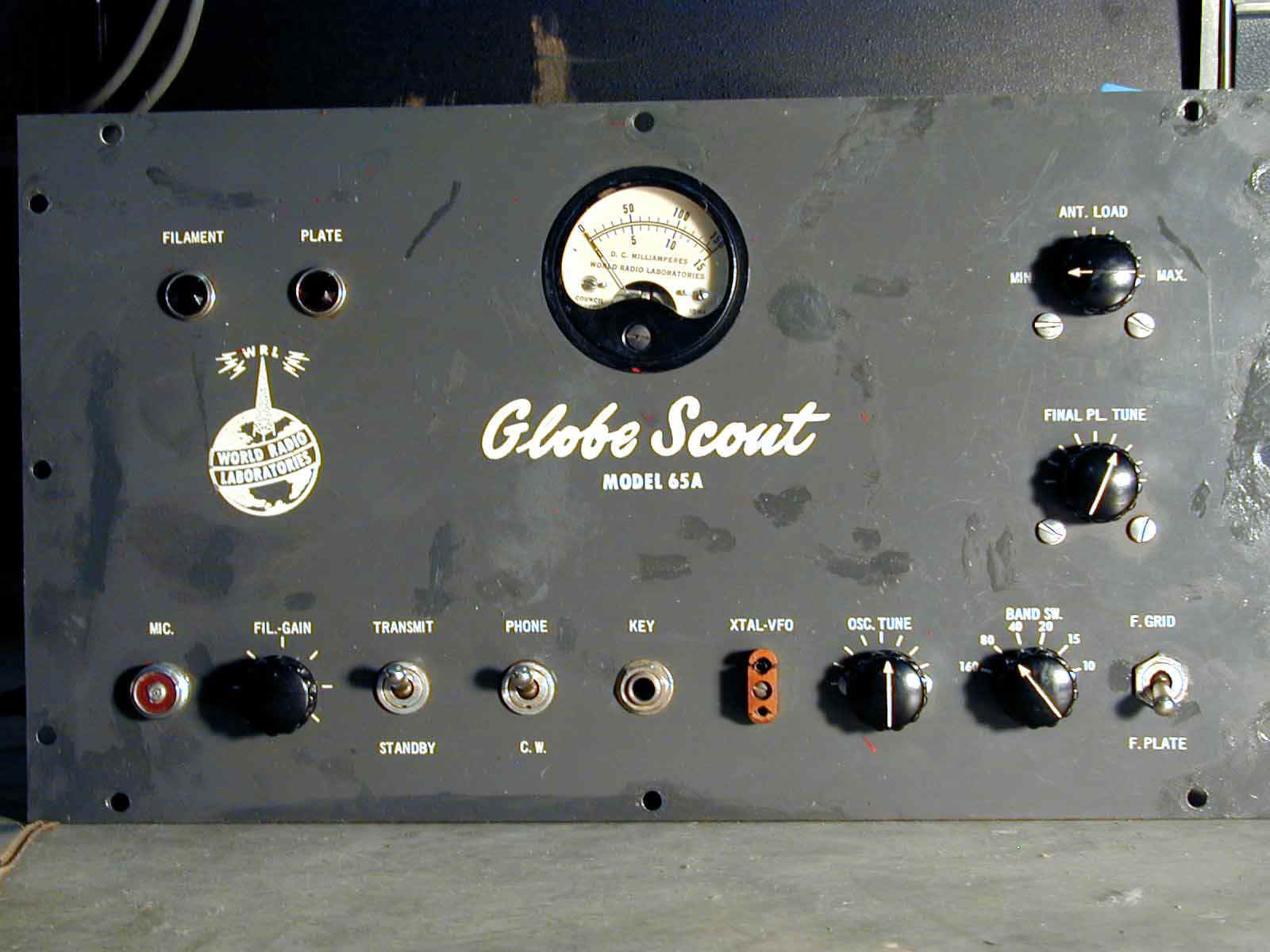
Front panel before rebuilding. The cabinet was worse.
I scanned this panel into Corel Draw and edited it there.
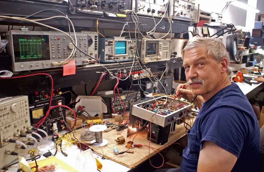
Globe on workbench undergoing audio sweep and distortion tests.
The little board on the bench on the red clip lead is a screen voltage shunt regulator.
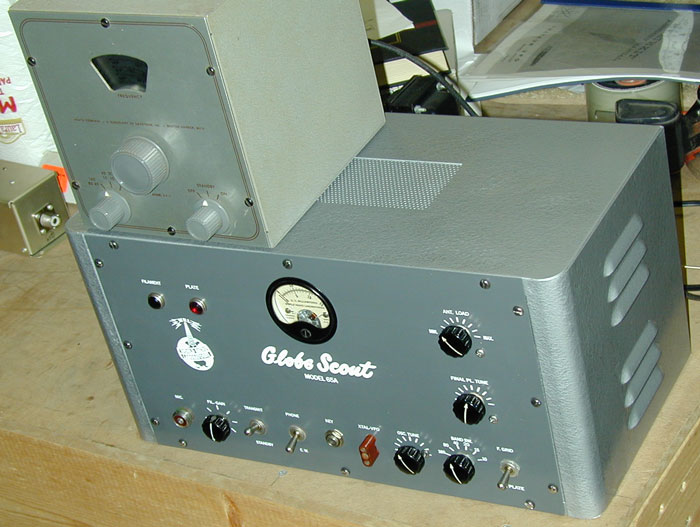
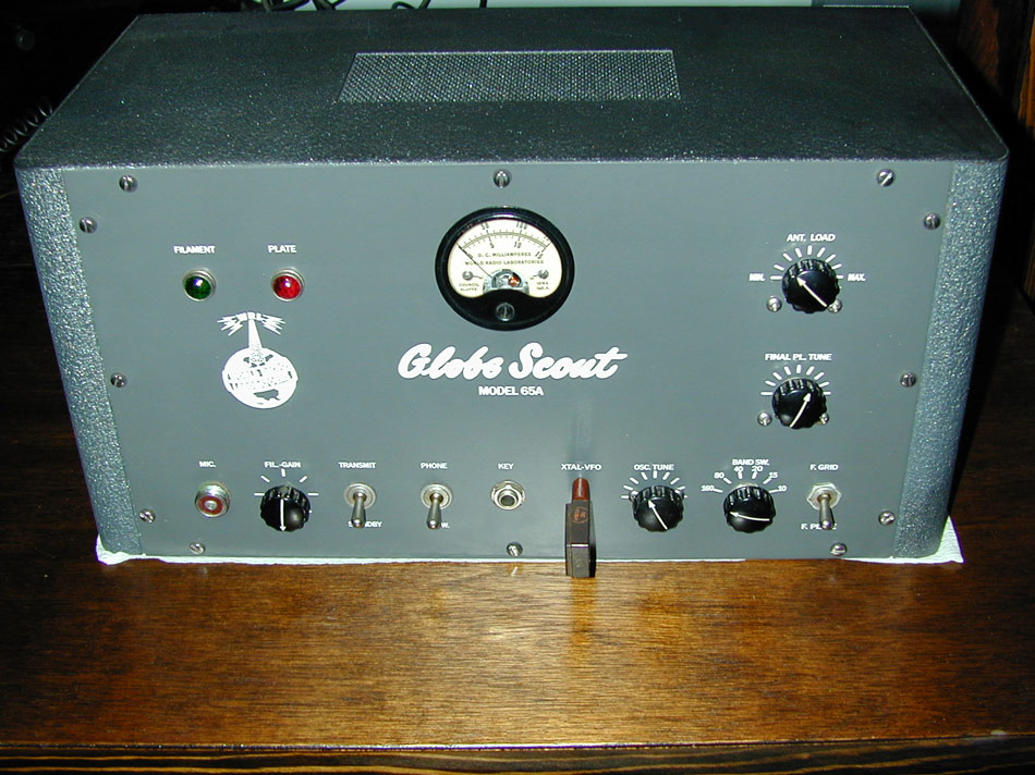
Front panel and cabinet after rebuilding. I did this all myself, including painting and screening. I have a limited number of spare refinished parts. They look exactly like new old stock parts. They are flawless reproductions.
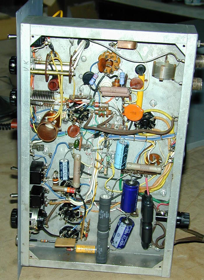
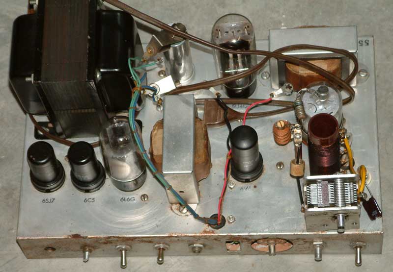
Under chassis view. This Scout 65A has grid block keying, stabilized low voltage system, and other improvements. It now runs over 60 watts output on CW, and 25 watts on AM phone with 100% modulation and good fidelity. There is even a screen regulator circuit up above the 6146 socket!
Keying is time-sequenced grid-block keying. The large orange .1 uF disk is part of the CW sequencing. It shapes the 100-volt keying voltage applied to the grid of the 6146.
The anode voltage of the 6146 is dropped on AM phone with the 450 ohm resistor removed from the tube's cathode circuit. The blue color axial lead capacitor is across the 450 ohm resistor.
This change increases effective CW anode voltage by 45 volts, because the 6146 cathode is now grounded. Bias is applied to the control grid, and the screen is regulated at 200 volts except when on AM, where it becomes unregulated at 150 volts.
Do not remove the factory 6146 cathode resistor without adding negative control grid bias!!
The chassis undergoing cleaning and reconstruction.
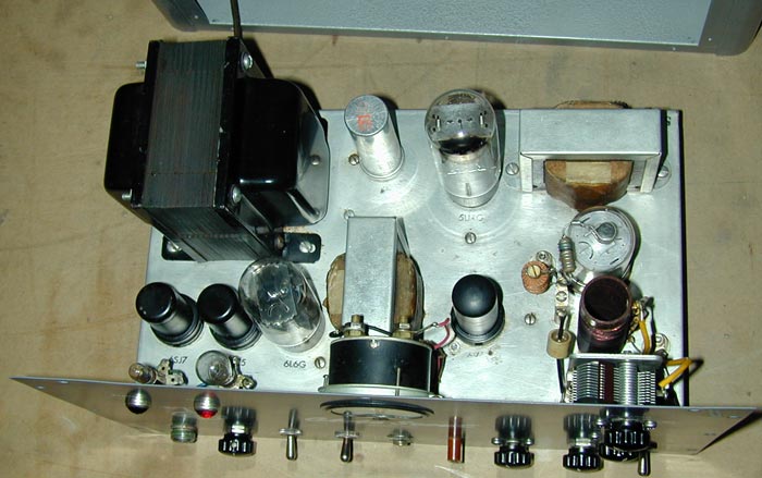
The chassis after cleaning and rebuilding. This is the appearance with ALL modifications. Notice no holes were added or components removed. Nothing visible above the chassis was changed except one component.
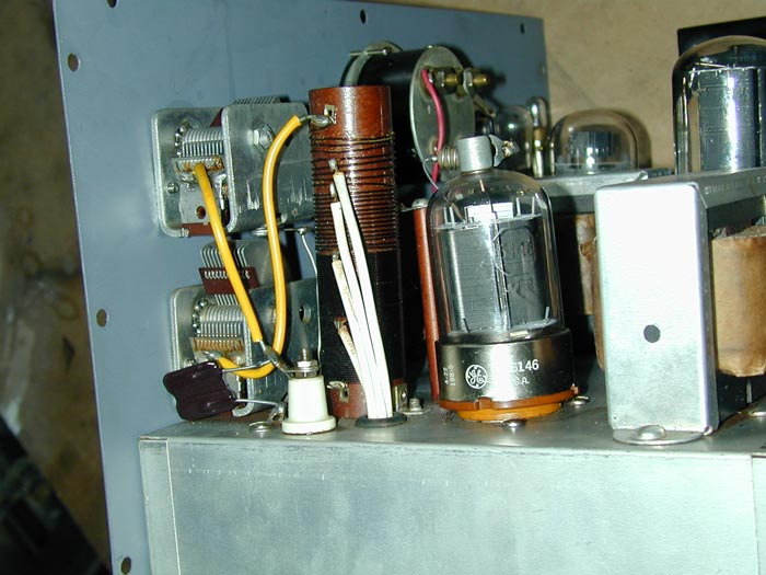
A single 180pF capacitor was added to improve loading. It is visible near the white insulator.
For 160 meters, I add an external screw-on capacitor on the COAX port, and feed the antenna from the DOUBLET port. On 80, the DOUBLET port loads fine. On other bands everything works normally, and the ANT or COAX port is used.
This Globe Scout 65A now makes nearly 70% efficiency on bands below 20 meters. Prior to mods, it did not load properly on 160 and 80.
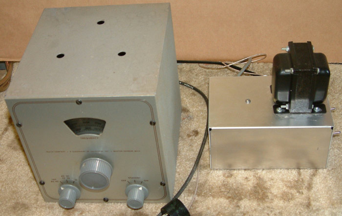
I use this VF-1 and homebrew power supply. The VF-1 is modified with a triode oscillator and tetrode buffer stage. It has time-sequence grid-block keying, and 50V P-P output to drive the drive-hungry Globe Scout 65A. Even with buffering, the Globe Scout 65 6V6 pulls the oscillator, giving the station a little bit of that old fashioned chirp common on some old rigs.
The final restoration, ready to install and operate. My first contact with the restored rig was VK3ZL on 160 meters. Big antennas really make a difference although I did work England, Germany, South America, and the Caribbean in 1963 with my Globe Scout 65A using a dipole 30 feet high from Ohio.
visits since created on September 19, 2004