|
Skip to tetrode and grid
driven amplifier neutralization
Neutralization, or lack thereof, typically causes one or more of the
following problems:
- Instability near the operating frequency
- Increased IMD
- Decreased efficiency
- Difficulty tuning
Grounded Grid Amplifier Neutralization
While
there may be
exceptions,
neutralization
of a high frequency PA
(power
amplifier)
vacuum tube
amplifier has little to do with VHF or UHF stability.
VHF
instability
is almost
always
caused by a
high
impedance
(or even parallel
resonant)
path from grid-to-ground. The
high
grid path impedance
prevents the
grid from
being held at
ground-potential for RF over some
range of
frequencies.
If the high
grid-path impedance occurs at or near a
frequency
range where
the anode
path to
ground is
parallel
resonant,
the tube can
act like a
tuned-plate
tuned-grid
oscillator.
Neutralization is primarily concerned with correcting unwanted
feedback that occurs from normal
anode-cathode feedback in a grounded grid amplifier. Anode-cathode
feedback is caused by imperfect shielding from anode to cathode inside
the tube, as well as additional feedback outside the tube. In reasonable
layouts the in-tube capacitance dominates, especially if multiple
parallel tubes are used.
Lack of neutralization causes the following problems:
- Instability at or around the operating frequency
- Increased IMD or distortion
- Loss of efficiency on higher frequencies
As in other amplifier stages and systems, excessive unwanted feedback causes the plate
current dip and maximum power output to be out-of-sync. This can add
positive feedback, increasing intermodulation distortion. In severe
cases, the amplifier becomes unstable and oscillates under some tuning
conditions at or near the operating frequency. The Yaesu FL2100 series,
the Dentron Clipperton L, and the Collins 30L1 amp with 811A tubes, are particularly
unstable designs. Collins and Yaesu have a particularly poor feedback
systems, while the Dentron has nothing at all!
In the FL2100, rumors are some tubes oscillate because they have
higher mu or gain. This is actually the opposite of the truth. The
FL2100 will oscillate, on standby, with any 572B tube if the bias is
reduced enough to allow conduction with the antenna and exciter
disconnected. The reason some tubes oscillate in the FL2100 while others
do not, while on standby, is some tubes have slightly lower mu and draw
current at idle while in standby. If bias is reduced on any brand tube,
the FL2100 series will break into oscillation. The HF instability has
little to nothing to do with gain, the instability is rooted in the lack
of neutralization in early FL2100's, and a
terrible neutralization
system in the later FL2100Z.
The worse thing about the incorrect mu rumors is the rumors mislead
people into thinking certain tube brands cause problems from gain
changes. The real problem is Yaesu used a terrible biasing system that
barely cuts the tubes off on standby, they failed to swamp or load the
tubes, or properly neutralize them. When Yaesu finally added a
neutralization system, they used a terrible system. They added feedback
from the antenna side of the tank circuit back to the filament. This
creates variable phase and level feedback, with feedback depending on
band, tank capacitor settings, and load impedance. This is as bad as the
RF feedback in some Collins transmitters that wraps back around two
tuned stages that are user adjustable.
In cases like this, where the design is flawed, blame is shifted to
the tube type, even though the real problem is in the equipment design.
In some Collins exciters, certain 6146's are blamed for a poor feedback
system that destabilizes the stages. In the FL2100, Svetlana 572B's are
blamed for Yaesu bias and feedback design problems. The result of this
is certain tube brands get a bad rap, often in well-written white papers
that, unfortunately, are based on speculation rather than logical
verification.
Long grid path of 572B tube and poor shielding from anode to cathode
(filament) structure:
The VHF parasitic circuit, unrelated to neutralization,
heavily involves the grid's path to ground.
Neutralization can only cancel Cpk, and generally has
minimal effect on VHF stability of HF power amplifiers. Lack of
neutralization, when required, causes upper HF instability. Upper HF
instability can easily damage band switches and other tank components.
Cathode
Driven Power
Amplifier
Many people
think
grounded
grid HF PA's
never
require
neutralization.
In many
cases this
is true, but
in some
cases it is
not true.
Tubes with
low
impedance
compact grid
structures
and grid
connections
that come out
of the
envelope with
very short
leads, like
the 8877,
have very
little
feedthrough
capacitance.
The 8877 is
unconditionally
stable all the way
up to UHF.
With the 8877
grid ring
grounded
directly to
the chassis
with a very
low impedance
connection,
the 8877 will
not require
neutralization
or parasitic
suppression.
Some tubes
are much
different. Tubes
like the
3CX1200A7 or
D7 have
significant
feedthrough
capacitance,
and exhibit
"out of
neutralization"
behavior
above 20
MHz. This
behavior is
characterized
by maximum
RF output
occurring
well off the
plate
current dip,
and in some
cases (i.e.
open circuit
input
terminations)
by actual HF
instability.
Tubes
generally
not
requiring
neutralization
in GG HF
amps are
the:
8877/3CX1500A7
8873 8874
8875
3-500Z
3CX800A7
3CX1200Z7
3CX3000
series
3CX5000
series
3CX10000
series
Tubes
generally
benefiting
from
neutralization
in HF GG
amps are
the:
810,
811A, 833,
572B,
100TH,
304TH, 8005,
3CX1200A7,
and
3CX1200D7.
Tetrodes and
pentodes generally
have very
low feedback
when their
grids
operate at
RF ground
potential.
Connecting a
beam forming
plate, screen
grid, or
control grid
to the
cathode
changes
things. With
a grid or
beam forming
plate tied
back to the
cathode,
feedback can
increase to
the point of
instability.
Some
amplifiers,
such as the Amp
Supply
LA1000 or
Dentron
sweep tube
amps, were
unstable on
ten meters
because the
control grid
was tied
back to the
cathode. While
these
amplifiers
could have
been
stabilized
through
neutralization,
the customer
was left to
simply load
them heavily
enough to
stabilize
them.
Tubes
with better
internal
shielding,
short
wide grid leads,
compact
grid
structures,
and close
spacings not
only work
better at
upper high
frequencies,
they are
also significantly
more stable
at VHF. Such
tubes
rarely
require
neutralization
or parasitic
suppression!
The most
stable tubes
are designed
to work at
VHF and
higher, the
least stable
tubes
generally
make poor
VHF
amplifiers.
How
Do We
Neutralize a
Grounded
Grid
Amplifier?
Electrical
Equivalent
Grounded
Grid
Amplifier
In
the circuit
above, T1
inverts
phase 180
degrees.
Cneu
approximately
equals Ckp,
the cathode
plate
capacitance
(or
feedthrough
capacitance)
of the tube.
Unwanted
feedthrough
capacitance,
Ckp, varies
widely with
frequency.
This
capacitance
is not
frequency
linear. It
has less
reactance at
higher
frequencies,
and higher
reactance at
lower
frequencies.
The absolute
equivalent
value of Ckp
varies more
than a pure
capacitor
would with
frequency
because all
stray
inductances,
including
Lint
(internal
lead
inductance)
and Lext
(external
lead
inductance),
cause Ckp to
have a
reactance
vs.
frequency
slope much
more rapid
than a
normal fixed
capacitor.
This means
we can
really only
neutralize a
PA perfectly
over a small
range of
frequencies.
In
the
Ameritron
811H
amplifier,
neutralization
is almost
perfect on
fifteen
through ten
meters. The
typical
feedthrough
null is 35
to 45 dB.
The 811H
neutralization does a
good job
from 7 to 45
MHz, where
feedthrough
is less than
-20 dB.
Feedthrough
capacitance
is so low
perfect
neutralization
is not
required below
10 MHz. Above 45 MHz
the parasitic
suppressors
load the
circuit
enough to
greatly
decrease
gain and
stabilize
the stage.
The AL-811H
is perfectly
stable and
will not
break into
oscillation
on any band
if
we remove
the antenna
or exciter, key
the PA
without
drive, and
rotate the
tuning and
loading controls
throughout
their range.
If
we repeat this
test with a
Clipperton
L, Yaesu
FL2100, or a
Collins 30L1
(all
un-neutralized
amplifiers)
most
amplifiers
(if not all)
will break
into
self-oscillation
on 15 and 10
meters. This
instability
occurs
because 811
and 572
tubes have
similar
poor construction.
The tubes have very
poor
shielding
from anode-to-cathode.
Both tube
types
exhibit very
high amounts
of
feedthrough
capacitance,
enough
feedthrough
capacitance
to make
un-neutralized amplifiers
unstable
near
the
operating
frequency on
higher bands,
such as 15 and
10 meters.
The circuit
above is a
typical
neutralization
system for a
grounded grid
amplifier. The
ferrite core is a 1 to
2 inch
diameter, 1/2
inch thick,
using a higher
Q (low loss
tangent) 61 or 65
material.
Test Setups
Neutralization adjustments are best done on a cold amplifier. To adjust
neutralization, three basic test configurations can be used:
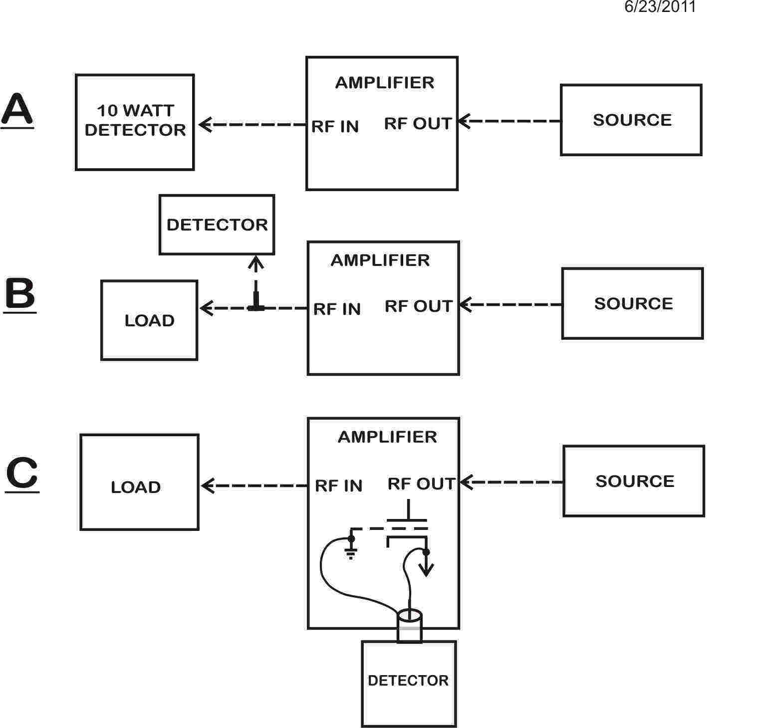
In all configurations except "C", input and output ports can be reversed.
The source should be variable, and capable of supplying a few watts.
Many transceivers will work OK.
The detector should respond to very low levels, but be capable of
withstanding some reasonable power in the event of a circuit or
component defect that accidentally allows full source power to couple
through.
See Grid driven
tetrodes
Grid
driven
tetrodes
like 6146,
807, or
4CX250's
have high
power gain.
High gain
systems
require very
little
feedback to
become
unstable, so
they
are generally
neutralized.
The also
often
require some
form of grid
loading
resistor to
reduce or
stabilize
gain. The
following
circuit
shows a
commonly
used tetrode
grid-driven
amplifier
with
neutralization:
L1/C1
is the
normal input
tuning coil.
Being
resonant on
the
operating
frequency,
it inverts
phase
180-degrees
from
end-to-end.
C2 is a
voltage
divider to
control the
feedback
voltage
ratio and
provide a
return path
for grid
excitation.
Cneut is
adjusted so
its voltage
feedback
equals the
voltage fed
through Cgp
from plate
to control
grid inside
the tube.
Note
that this
system
depends
heavily on
L1/C1 being
resonant at
the
operating
frequency.
This proves
the tube is
only
neutralized
at the
frequency
where C1/L1
is set. It
does not
stabilize
the tube on
any
frequency
except where
L1/C1 is
resonant.
Lp,Lsc,Lk,
and Lg are
inductances
of leads
inside the
tube.
Lp1,Lg1,Lk1,
and Lsc1 are
lead and
component
inductances
that occur
outside the
tube.
While
the feedback
adjustment
setting of
Cneut holds
true for
multiple
bands near
the initial
adjustment
frequency,
it only
actually
neutralizes
the tube on
the band in
use at any
moment of
time!
In
a 160-10
meter PA,
Cneut
generally
only works
properly
over two or
three bands.
It is
usually set
near 15
meters so it
has the most
effect where
it is needed
most. By
the time we
get down to
40 meters
and lower,
feedback
voltage
through Cgp
is generally
through such
a high
reactance
that the
lack of
proper
balancing is
meaningless.
Additional stability can be added by loading the grid
with a broadband termination resistance. This makes neutralization much
less critical, and may at times even eliminate the need to neutralize.
This resistor would go from the control grid to ground and ideally be
added right at the tube. Unless the resistor is an integral part of the
bias system, it must be "dc blocked" with a low impedance series
capacitance so it does not affect grid bias.
Neutralization
Neutralization
generally
only affects
operation
near or at
the desired
operating
frequencies.
Neutralization
is normally
optimized
near the
upper
frequency
end of
operation,
perhaps
between 15
and 30 MHz
in a 1.8-30
MHz
transmitter
or
amplifier.
Neutralization
is sometimes
needed
because
tubes have
unwanted
internal
capacitances.
The
capacitance
between the
output
element and
the input
element
inside the
tube will
cause the
output
circuit to
couple back
to the
input. If
large
enough, this
regenerative
feedback
could cause
a loss of
efficiency.
It might
cause the
output
maximum to
occur off
the plate
current dip,
reducing
efficiency.
It might
increase IM
distortion
or in rare
severe cases
may cause
the
amplifier to
oscillate
someplace
the
operating
frequency.
(This
problem is
common with
grounded
grid
amplifiers
using 572B's
like the
Dentron
Clipperton
L, or
quads of
811A's, like
the Collins
30L1. Yaesu
has this
problem is
some
FL2100's.)
While a
need to
neutralize
does occur
in some HF
grounded
grid
amplifiers,
it is more
common in
very high
gain
grid-driven
amplifiers.
Neutralization
Adjustment
Methods
Neutralization
is generally
accomplished
by adding an
external
capacitance
that is
excited
exactly 180
degrees
out-of-phase
with the
feedthrough
capacitance.
One typical
adjust
procedure is
to disable
the PA stage
by removing
anode and screen or
filament
voltage. A
sensitive RF
detector is
connected to
the
transmitter
output.
Neutralizing
a totally
cold tube is
perfectly
fine,
because
there is
very little
capacitance
shift in a
tube with
temperature
changes.
Normal
drive is
applied, and
the
neutralizing
capacitor is
adjusted
until
feedthrough
power is
minimum. The
tuning
controls are
continually
peaked for
maximum
power on the
sensitive
detector
throughout
the process.
A second
less
accurate
method is to
watch the
plate
current dip
in a
properly
tuned
normally
operating
transmitter.
The
neutralization
capacitor is
adjusted
until maximum
power output
and minimum
plate
current occur
simultaneously
as the plate
capacitor is
tuned.
The best
method
varies with
the PA
design, but
in general
the most
accurate
method is by
applying
drive to a
cold PA
stage
(generally
either
screen and
plate or
filament
power is
removed) and
feedthrough
power is
measured
with a
sensitive
detector.
What
Happens If
We Don't
Neutralize a
New Tube?
Many
times
nothing
noticeable
occurs if we
don't
neutralize a
PA. The
results
really
depend on
how much
different
the internal
capacitance
is in the
new tube(s)
when
compared to
the
capacitance
of the
tube(s)
being
replaced.
If the PA
requires
neutralization
and we don't
neutralize
or
re-neutralize
it, we could
find IM
distortion
higher. We
would
probably
find maximum
output power
occurs
well-off the
plate
current dip.
The
un-neutralized
stage, in
severe
cases, might
oscillate
somewhere
near the
operating
frequency
under
certain
conditions
of tuning
and loading.
Neutralization
is generally
only
accurate
over a
limited
range of
frequencies,
but
fortunately
it is almost
always at
the higher
frequency
end of the
operating
range where
the PA needs
neutralized.
The
manufacturer
probably
knows the optimum
adjustment
point. In
the AL1200
and AL811H,
the optimum
null
frequency is
21.5
MHz.
|