|
Neutralizing AL811H Amplifier
Re-neutralization is normally not required when tubes are
replaced with similar construction and same-type tubes. If tube construction is
different, or you change tube types, neutralization should be checked. Improper
neutralization increases distortion (splatter) on higher bands, and can reduce
stability or efficiency on higher bands.
With grounded grid amplifiers, the PLATE tuning control
only provides a very rough indication of proper neutralization. PLATE control
behavior is not entirely reliable in grounded grid circuits,
especially with lower-mu tubes, because amplifier input impedance is directly
affected by anode current. The input match change as plate current varies causes
a changing exciter SWR match to the amplifier input. This causes drive power
reaching the tube to vary with output tuning adjustments. This can move maximum
output power outside the bottom of the plate current dip when tuning, even in a
perfectly neutralized amplifier.
| Note: While setup is more
involved, the following procedure is safer. The following procedure is
also far more accurate than the commonly-used method of looking for
maximum output at minimum plate current (middle of plate dip) !
|
Equipment required:
Any one of the following three items:
- Spectrum analyzer (preferably with marker amplitude-delta
display), sensitive diode detector system, or oscilloscope capable of good
sensitivity up to 30 MHz
- Low current or current limited 13-18 volt power DC supply with clip
leads
- Typical electronics hand tools
- 50-watt or higher, 50-Ohm Dummy load
- -10 to -20 dB bridging tap for spectrum analyzer
- Transceiver with SWR meter and/or MFJ 259 analyzer or equivalent
|
Warning:
Do NOT connect amplifier to the
power line during any part of this process!
Be sure your test equipment can
take the power levels and voltages applied
|
Work in a clear area with good lighting. Be sure amplifier
is unplugged and remains unplugged throughout this adjustment procedure, and HV
meter reads zero. Then remove amplifier cover.
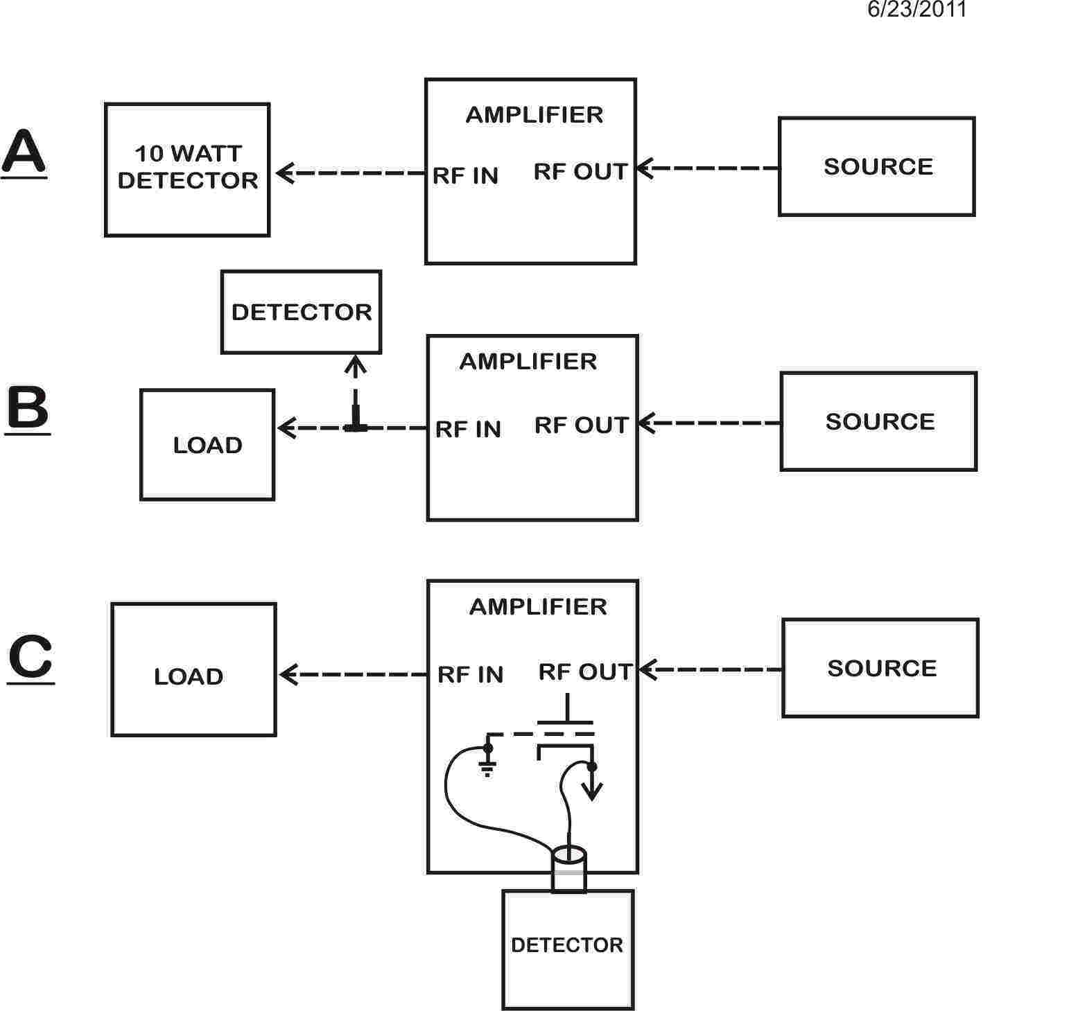
Connections
An MFJ-259 can be a source, if you have a sensitive detector system. A
receiver with S meter will work as a sensitive detector. There are three test choices:
- In lieu of sampling
at the output and accidentally driving the load or detector with full
exciter RF, a lower risk sampling method would be to wire wrap tube pins
and sample from a tube filament or cathode. Setup C
- If your detector
system cannot safely handle exciter or RF generator power,
connect a dummy load to the amplifier’s input port. Connect the detector
through a bridging tap on the dummy load feed line. Setup B
- If your detector can handle full exciter or RF
generator power without damage, connecting the detector system directly
to the RADIO input port is acceptable. Setup A (Detector power rating
below assumes your source will never exceed 10-watts. If your signal
source can exceed ten watts, use a suitably rated detector. The most
common issue is finding a high power detector that is very sensitive at
low signal levels.)
Connect a transceiver or low power RF source to the amplifier’s RF Output or
Antenna port. This is reversed from normal connection
1.) Connect the amplifier’s transmit relay control line, or RLY jack
center pin, to chassis ground
2.) Set the bandswitch on 15 meters, and generator or radio on or near
21.5 MHz, or the high end of the 15-meter band
3.) Connect a dummy load or detector, that safely handles exciter power
levels, to the amplifier’s RF input port. This is backwards from normal,
the radio or generator drives the amplifier OUTPUT port
Early 811H with single relay:
4.) Connect the 13-18 volt positive supply line to the meter lamps. In
the AL811H, at the time of this writing, this is a yellow wire that leaves
the meters and terminates on the STBY/OPR switch. The negative power supply
line connects to chassis ground. This supply will operate the relay. Watch
meter lamps and apply +13 to +18 volts. The meter lamps should illuminate.
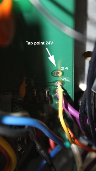
Later AL811H with dual relays:
4.) Connect an 18-24 volt low-current power supply to the transformer 10
VAC control and DC LV winding, or to the 12VDC and 24VDC supply terminals. In newer AL811H amplifiers,
the 24VDC is an empty pad just above a yellow
wire (12VDC), and the yellow wire. The negative power supply line connects to chassis ground. This supply
will operate the relay. Meter lamps will illuminate with any 12VDC
connection.
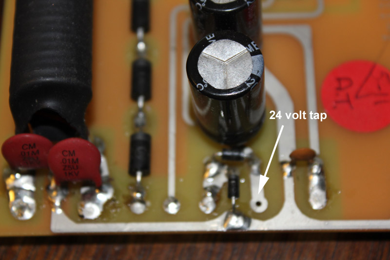
This is the early dual-relay board.
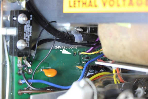
This is the most recent AL811H board. Scheduled production
release is fall 2012.
5.) Be sure the amplifier BAND is set to the fifteen
meter position, LOAD on 2, and PLATE on 9. Leave
the amplifier on STBY.
Connect the detector. The following is the BEST detector connection method.
It will work with a normal 50 MHz or higher rated oscilloscope.
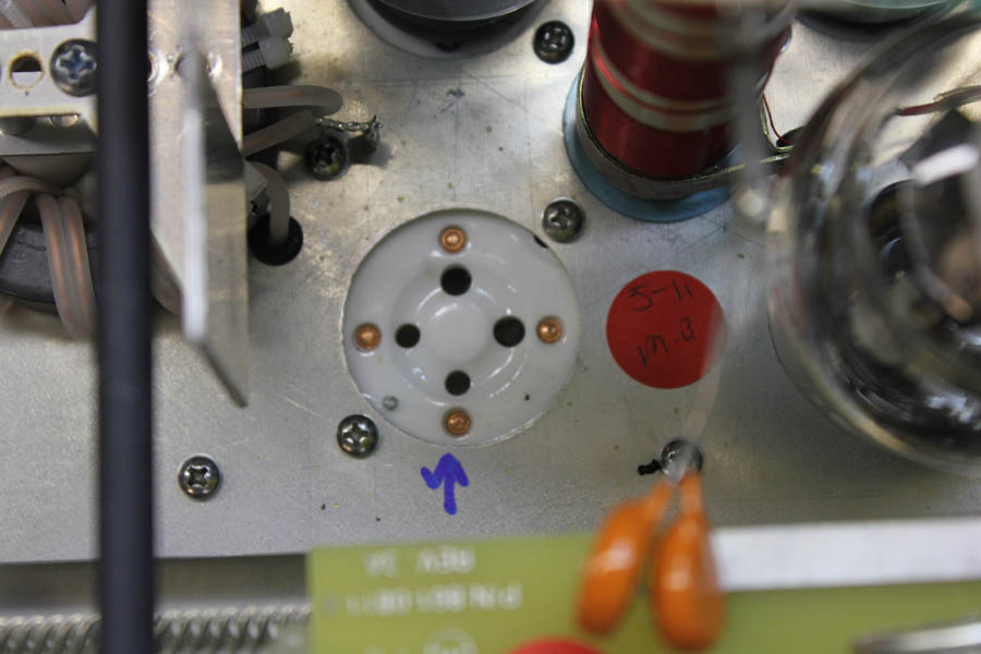
Remove tube from socket. Blue arrow is grid pin.
Because Chinese tubes and sockets, which all tubes are now, have sloppy
pin and hole tolerances, it is sometimes possible to insert tubes incorrectly. Be sure
to align small pins with small holes.
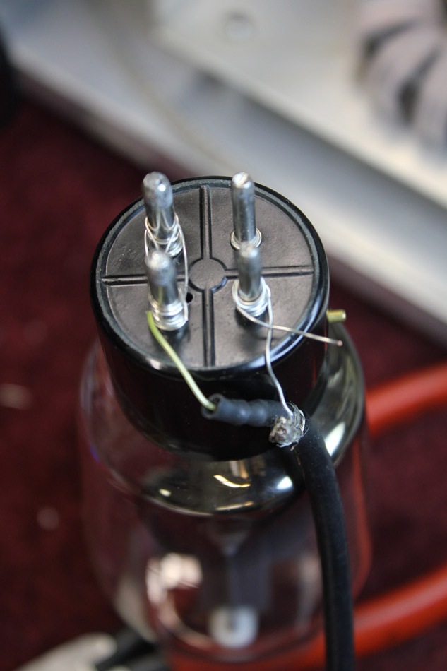
Wire wrap tube pins to make temporary connection. Use the shortest leads
possible. Note the sample is shield to grid pin, and center to shorted filament
pins!
Leads should exit as shown.
Alternatively, a scope probe can be connected as show below:
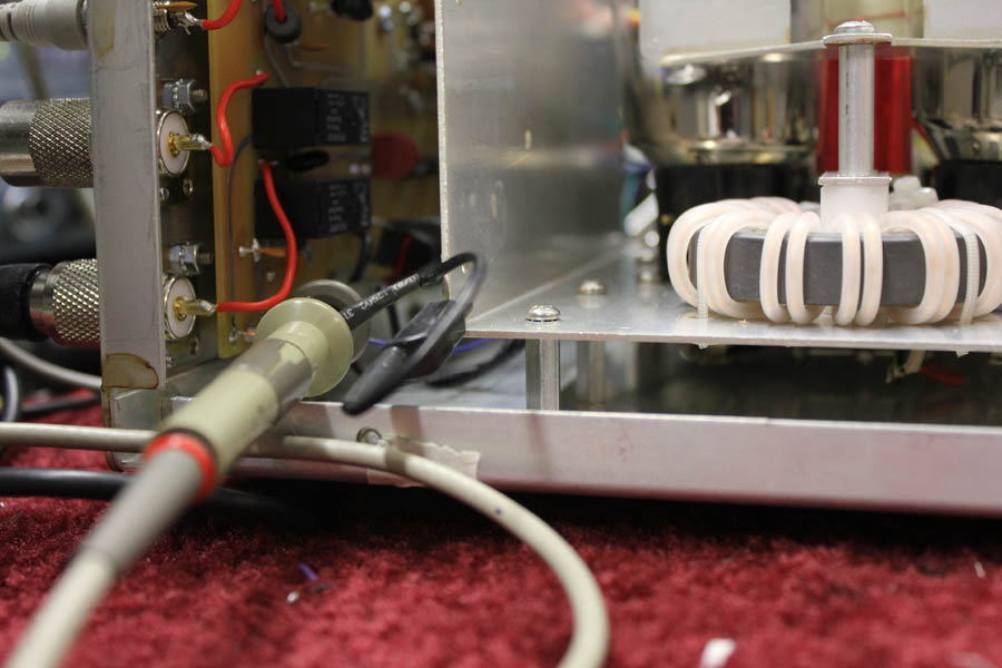
The scope probe clips to a filament choke wire
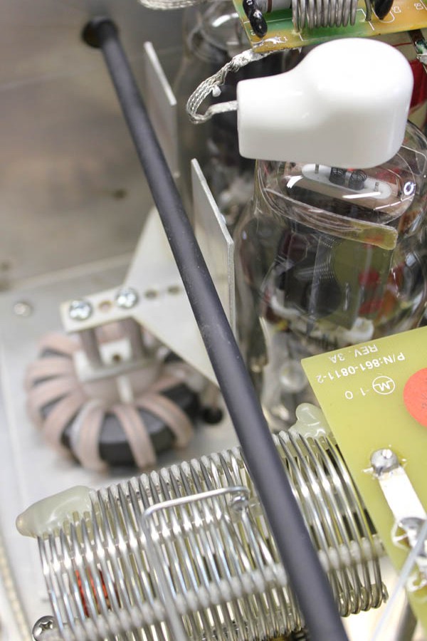
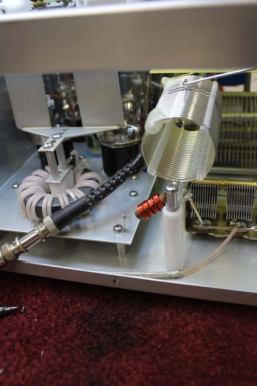
This is the neutralizing capacitor. It is adjusted by moving closer to, or
away from, tube envelope.
Coarse adjustments are made by changing plate mounting to various screw
holes. Fine adjustments are made by carefully bending plates.
|
Critical Safety Warning:
Always be sure amplifier is
unplugged from mains, and high voltage has reached zero volts on the HV
meter, before removing amplifier covers or panels.
Never remove panels or covers, and never
work inside the amplifier, with the amplifier connected to power mains!
There is never a reason to operate the amplifier, or connect the
amplifier to power mains, in any trouble shooting or adjustment
proceedure.
|
Procedure
Note: The following procedure is far more accurate, and
less tedious to accomplish, than the commonly-used method of looking for maximum
output at minimum plate current (middle of plate dip) !
1.) Be sure the signal source is near 21.5 MHz.
2.) Adjust generator or radio for less than ten watts carrier, or
whatever level can be safely detected (not to exceed ten watts)
3.) With amplifier on OPR, and RLY line grounded (either through radio or
direct), the XMT light should glow and the relays should click
4.) Observe SWR meter on radio or generator and adjust PLATE and LOAD for
lowest SWR (or maximum detector reading). Use minimum power that gives
reading, and never exceed ten watts power. SWR
should tune to perfect match by adjusting the tank circuit
5.) Observe the indicated level. Moving the two tubes nearest the
neutralizing plate toward and away from the plate, either by rocking the
tubes forward and back with a non-conductive non-metallic rod should clearly
change indicated level
6.) The goal is to adjust neutralizing capacitor position and spacing for
minimum indicated power on the RF detector. There should be a very definite
minimum
If tubes are rocked slightly away from the neutralization plate, and RF level
is still decreasing, move the neutralizing plates farther away by slightly
bending the plates or using different screw holes.
If the tubes are moved against the neutralization plates and level is
decreasing, bend or move the plates closer to the tubes. The goal is to have a
dip in coupling from generator to the detector when the tubes are seated flat in
the sockets.
-
When finished, tubes should seat normally in the sockets, the plate should
clear the tubes, and the difference between plates installed and not installed
(no neutralization) should be at least 20 dB. (10:1 voltage ratio). Typically,
the null should be better than 30 dB on fifteen meters.
Best neutralization may not result in plate current dip and maximum output at
the same spot, but they will be close.
 ©2012 W8JI
|