Vacuum Tube Failures
Related pages:
Sales link CTR Engineering Inc.
HV arcing peak voltage when mistuned
Page Down Links
Power grid vacuum tubes are used in amplification systems where
grid to cathode voltage controls plate (anode) current. The system can be linear
or non-linear, it can be an amplifier or a regulator. Essentially the tube acts
like a variable resistance in series with a diode, the cathode to anode
"resistance" controlled mostly by the grids. The tetrode or pentode, when
operated normally, is a "stiffer" resistance with regard to anode-cathode
voltage. Triodes are quite a bit "looser", the anode-cathode voltage having
somewhat more influence on anode-cathode "resistance".
Power-grid
vacuum tubes cover a
wide range of
applications. A
wide variety of
styles have evolved
over the years.
Every tube design is a
compromise of some
type, designed to
better fit a few specific applications or improve certain characteristics. For
example, there are
dozens of grid and
cathode (electron
emitter) designs.
There are a wide
variety of anode
styles and types.
Even the heaters or
filaments have
many shapes, materials,
and characteristics.
Transmitting tubes typically operate at fairly high voltages. 1kV is about the very least we find in modest power amplifiers, while high power amplifiers can run at 20 kV or more. The normal peak anode voltage, in a typical class AB amplifier, is nearly twice the dc anode voltage. This means the tube has to withstand several times the maximum dc voltage applied to the stage. I consider a 3-500Z tube good when the anode holds off at least 8kV in a static leakage test. This requires a very hard vacuum. The slightest amount of gas will significantly reduce breakdown voltage.
The big enemy of large glass envelope vacuum tubes that
have not been regularly operated is gas.
This is especially true with graphite anode tubes and tubes with large pins. The porous graphite
tends to slowly release trapped gas over time. Glass envelope transmitting tubes generally use a Kovar coated wire or pin. The Kovar coating allows bonding to a special composition glass. Tubes with large diameter Kovar coated pins protruding through bonding compatible (borosilicate) glass, such as 4-250A through 4-1000A style envelopes, often develop storage failure from gas ingress through seals. Kovar seals are sensitive to humidity, and most transmitting tubes only getter or degas during actual operation. This is why new old stock glass transmitting tubes are very high risk for gas-arcing. As pin diameter increases seal leakage becomes more problematic. An 811A is fairly low risk, while a 3-1000Z is fairly high seal leakage risk.
I was at a flea market with a friend in the 1970's. My friend purchased brand new in box 3-400 tubes with an old code date, I purchased the fresh used pull outs with a similar manufacturing code date. When we tried the tubes, his NOS tubes were gassy. My pull out tubes were perfect. NEVER buy old glass tubes without some agreed warranty!
The big enemy of high gain power grid tubes (or valves) using metal oxide cathodes is grid current and excessive cathode current, or low cathode temperatures.
The common problems of both types will be discussed in more detail below.
No one likes to waste money, or see parts go bad. In an effort to help others have longer tube life, occasionally claims that "running tubes easy will increase tube life" appear. That might or might be true, because it depends on the tube type and what is "hard" and what is "easy". There are many cases where running "easy" can shorten tube life, and some cases where running "hard" can damage a tube in seconds.
Bad information is everywhere, and sometimes accepted as fact. The ARRL, as careful as they sometimes try to be, has published more than a few incorrect articles about amplifier and tube life. It is easy to see how this happens, because few people keep meaningful statistics, and few seem to intimately understand vacuum tubes and amplifiers. it is a dying science, like general electronics knowledge, because few are interested in why things happen, and some of the curious never actually measure what they claim to be measuring.
Tube Types and Life (overview)
A thoriated tungsten filament tube can be run "hard", to the point
of complete filament-cathode emission saturation, and the life will be no shorter
or longer than when run easy, provided the elements being bombarded by electrons
or the envelope does not overheat and suffer permanent thermal damage. We can
lower filament voltage in a thoriated tungsten tube, and provided it doesn't
get contaminated from prolonged operation at excessively low voltage, all that
happens is peak clipping.
A metal oxide cathode tube can quickly suffer damage if operated that way. This
is why they sometimes have to start on a timer that prevents current before the
cathode is fully heated, which sometimes can be the warm-up time of a rectifier
tube and other tubes in the system! Lower the filament voltage in a metal oxide
cathode tube too low, and you can ruin it in seconds!
Within emission and thermal damage limits, tubes basically do not wear any
faster or slower if just idled or operated. It isn't like a mechanical engine,
where high RPM operation greatly increases wear by mechanically loading internal
parts increasing friction. As a matter of fact, too cold is often much worse
than hot.
There was an RCA transmitter that used a 4-400A in a driver stage, and the tubes
had chronic failures. This was because the anode never showed color. At Eimac's
suggestion, RCA changed to a lower dissipation tube in that tube family and life
became normal. The anode ran a little red, and life increased.
The single most common problem today with tubes is like with anything else, poor
quality control of materials (ingredients), unsanitary assembly, and poor
conditioning, testing, or aging. Most tubes come from the same few places, and
just have different external labeling or "features", while the insides are the
same with the same problems.
The days of 20-year tubes are pretty much gone, and won't come back by any
change made after the assembly process. The common premature failure problems
cannot be weeded out, operated out, or adjusted out. Poor operating, where an
anode is melted, is controllable. Tube labels, retailers, or other things we do,
unless grossly wrong, make no overall difference at all for most tubes.
While manufacturers use a variety of numbering systems, most Eimac tubes use an easily decoded system.
First number = number of active elements in the tube
2=diode 3=triode 4=tetrode 5=pentode
First letter = envelope type
nothing or - = glass
C = ceramic
Second letter = anode type
nothing or - = internal
X = external
W = water
V = vapor
Number group = anode dissipation (actual dissipation can be higher than the tube-type number, so check the books)
Last letter = Base or connection type
Blank = pins or tabs
A or Z = coaxial or pins
F = flying leads
Last number = mu, where 1 = lowest mu through 7 = highest mu
1 through 5 are best suited for grid driven applications
7's are best for cathode driven
From this we see a 3CX3000F7 is a triode with ceramic envelope and external anode, has approximately 3000 watts dissipation (in fact dissipation is 4000w), has flying leads, and highest mu of the 3CX3000 group (most suitable for grounded grid).
In addition, some tubes have additional letters inserted in the type number. Examples are the 4PR1000 or 3CPX800A7. The P generally signifies pulse rating, and the R more rugged construction.
Power-grid vacuum tubes operate by a thermionic emission process. In a vacuum tube, we commonly call the electron emitter a "cathode". The cathode can be directly heated or a filament-cathode. Another type is the indirectly heated, or heater-cathode type of electron emitter.
The cathode, regardless of sub-category, uses a material easily able to "give-up" electrons with heat. The cathode is heated in a nearly perfect vacuum to temperatures from around 1000K (we would see that as a red glow) to as high as 2600K (a yellowish-white glow). This heat supplies energy to loosely bound electrons at the cathode's surface, causing some electrons to escape the cathode material. These electrons form a cloud suspended around the cathode.
Commonly Used Cathode Materials
| Material | Operating Temp Range K | Emission mA/watt | Emission mA per cm^2 | Special Features |
| Pure Tungsten | 2400-2600 | 2-10 | 100-1000 | Immune to positive ions, can be operated at highest anode voltages. Instant on. |
| Thoriated Tungsten | 1800-2000 | 50-100 | 700-3000 | Much higher emission, but less immune to positive ions. Can be operated at reduced filament voltage or operated with peak currents over emission limits with little effect on life. Instant on. |
| Oxide-filaments | 1000-1100 | 200-1000 | 400-3000 | Very high emission per watt of filament power, but extremely sensitive to positive ions. Emission failures occur from low temperature operation if electron cloud is depleted. Must be thoroughly warmed up before any current is drawn, but warm-up time is short. |
| Oxide-cathodes | 1000-1100 | 10-200 | 1000-3000 | High emission in small cathode. Long warm-up time. High peak emission for pulse applications. |
Positive ions are formed through ionization of residual gasses. High anode voltages speed formation of positive ions. The space charge (electron cloud) surrounding the cathode repels positive ions, and keeps the ions from poisoning the cathode. When positive ions contaminate the cathode, electron emission is reduced.
Tungsten has the highest melting temperature of any metal, above 3600K. Tungsten has the ability to operate at high temperatures for many hours without evaporation of materials becoming a major problem. Tungsten is one of the few materials able to withstand total depletion of the electron cloud in a vacuum tube. Tungsten emitters are not damaged by stripping away of electron clouds, and the resulting cathode bombardment by positive ions. This immunity to damage means emission life is not shortened by excessive current, operation before full temperature is reached, or low filament voltage.
If a cathode material sensitive to positive ions is operated with excessive HV, or has excessive cathode current for the cathode operating temperature, it will suffer emission failure. This is why indirectly-heated tubes or oxide-cathode tubes must have long controlled warm-up times before any cathode current is drawn. We must NEVER operate the 3CX1500A7/ 8877, 3CX800A7, or other oxide-cathode tubes at reduced heater voltage! This would allow the cathode's protective electron cloud to be depleted, and nothing would prevent positive ions from striking and poisoning the cathode.
The anode is operated with a positive potential. This creates a strong electric field to the more negatively charged cathode. This electric potential difference causes an electrostatic (truly static at any frozen instant of time, but changing over time dynamically) field that attracts electrons from the cathode.
The grid or grids set up a static field surrounding the grid wires. This field, because it is between the anode and cathode, changes the field difference between the anode and cathode. It really becomes a multi-part system, with the grids changing the potential difference the cathode "sees". Cathode electrons from a cloud formed around the cathode are either accelerated or slowed as they pass through the opening in the grids.
Cathode electrons eventually strike the anode at reasonably high velocity. Since the electrons have mass and speed, they have kinetic energy. This energy produces heat, as well as dislodging other electrons from the anode. The amount of heat is proportional to the velocity and number of electrons. The dc electrical power converted to heat is anode voltage times anode current, at any frozen instant of time.
The actual plate dissipation, or plate heating, is the time-integrated product of anode current times voltage over a long period of small samples of time.
| Handbooks tell us
anode dissipation is plate input power minus RF output power. While that
method does not include everything, it is a way to reasonably estimate anode dissipation. In large high-power tubes, elements like the filament and screen grid heat the anode. That heat is generally small, although in directly heated external anode tubes the filament to anode heat transfer can be hundreds of watts. In operation with large transmitting tubes, we can ignore the small filament or grid heat transfer to the anode. Usually, the vast majority of anode heat comes from kinetic energy of electrons as they strike the anode. This heating is much like the heating of a resistor, and follows voltage times current at any instant of time. If, at any instant of time, anode-to-cathode voltage accelerating electrons is 3000 volts, and at that very same instant of time anode current is 200 mA, heat at that instant of time is 3000 *.2 = 600 watts. This is true for EVERY instant of time during tube operation! The actual time-averaged heating is the time-integrated value of the continuously varying anode dissipation over many thousands of full plate current cycles. The time has to be long enough to get a good "sample" of heating. With a typical AB2 class 3-500Z, running at maximum power with 3000 volts, maximum instantaneous plate-to-cathode voltage is around 5500 volts. At this voltage, anode current is at zero (or nearly zero) current. Dissipation at the instant of peak voltage, or near peak voltage, is 5500 * 0 = 0 watts (plus filament and grid heat transfer). The same system would have maximum anode current as minimum anode voltage is reached. Minimum anode voltage might be 500 volts, with 1.2 amperes of instantaneous current. This would be, at that instant of time, 600 watts of heat (plus filament and grid heat transfer). The large area of the anode of the anode has significant thermal mass. The thermal mass "smoothes" heating out to an average value over time. The actual concern is time-averaged heat over many seconds of time. Depending on anode style, averaging time can somewhere around 15 to 45 seconds with 3-500Z tubes. This averaging is important, because it limits anode temperature during overloads. 1000 watts of dissipation for 10 seconds causes no more heat problems than 500 watts would for 20 seconds, or 250 watts for 40 seconds. At some point heat escaping the anode, in the case of a 3-500 mostly through infrared radiation, places anode temperature in equilibrium. If thermal equilibrium is reached at a safe temperature, the tube can handle that power for limitless time. Dissipation is closely related to anode waveform and anode current pulse width. Class A amplifiers have steady average anode dissipation, with anode current producing heat over the entire signal cycle. The time-integrated, or time-averaged anode dissipation, is steady at some level. At the other extreme, Class C amplifiers can have much less anode heat. The anode is close to being either off or on, like a switch in series with a small resistance. Averaged anode dissipation is much less for a given signal output power than a more class A amplifier, since the class A amplifier spends a long time in an area where dissipation is high. |
In an amplifier with steady current, anode dissipation is found quite easily by multiplying the accelerating voltage (anode-cathode potential) times anode current. In an amplifier system, dissipation is a complex function of the constantly changing anode voltage and current. In such systems, a very close approximation of anode dissipation is given by multiplying average anode current by average anode voltage, and deducting the useful power extracted by the load.
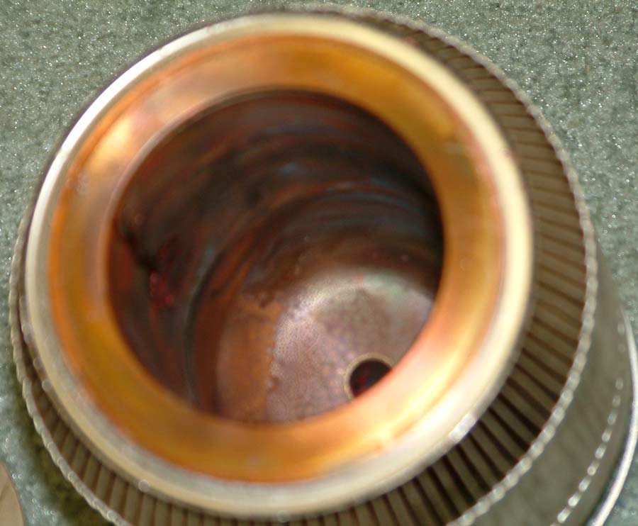
The following picture is the internally damaged anode of a YC-156/3CPX5000A7 tube. This tube was operated from a large power supply that had a string of 1 ohm 2 watt fault resistors:
Many lower power tubes use internal anodes. Internal anode tubes can use any electron emitter or grid configuration, although the most common large transmitting types use thoriated-tungsten filament/cathodes. Internal anode tubes are cooled by infrared radiation, by direct thermal conduction to the envelope, and through external connections via leads exiting the envelope.
The anode often serves three very important functions in a transmitting tube:
The anode collects most of the electron current from the electron emitter in the tube (cathode)
The anode must dissipate heat produced from kinetic energy of electrons that strike the anode
The anode often degasses the tube
The material used in the anode varies with tube type and manufacturer. Most transmitting tubes use molybdenum, tantalum, graphite (carbon), or other high temperature materials in the anode. The material must be mechanically and electrically stable, even while operating with very high temperatures.
In
transmitting tubes,
virtually all anode
heating comes from
the kinetic energy
of electrons
striking the anode.
The actual
resistance of
materials in the
anode (and other
elements in the
tube) is very low,
and the relatively
small amount
of ![]() heating is dwarfed
by heating from
electrons smashing into the anode surface.
heating is dwarfed
by heating from
electrons smashing into the anode surface.
Higher power internal anode tubes almost always have a gettering material coated directly on the anode. The getter acts as a sponge, soaking up any gas molecules inside the tube. This is necessary because any gas creates positive ions, reducing tube life. Not only that, even the slightest amount of gas greatly reduces breakdown voltage through a vacuum.
The most common gettering material is zirconium. For example, zirconium is used on the outside of graphite or molybdenum anodes in 3-500Z and other tubes. It is the dull gray powdery or grainy texture coating you see on the surface of 3-500Z, 811A, and 572B anodes.
Zirconium getters best at about 1000 degrees C, this is why large metal anode transmitting tubes like the 4-400A, 4-1000A, and 3-500Z must be operated with a dull red to red anode color. Zirconium also releases some gasses and absorbs other gasses at various temperatures. The varying temperature across the length of the anode (and as the anode heats and cools) allows the gettering agent to absorb a wide variety of gasses.
The quickest way to ruin a 3-500Z, or other glass power grid tube, is to never show anode color over a prolonged period of time! Storing a 3-500Z for many years without operation almost guarantees a flash-over will occur at the first application of high peak anode voltage.
Gas, either from poor manufacturing processing, out-gassing from elements, or seal leakage is the primary failure mode of glass tubes. Secondary to high-vacuum (gas) arcs are problems like bad welds or grid or cathode materials that fall out of alignment due to thermal or mechanical stresses.
We commonly associate external anodes with expensive tubes having fragile low-dissipation grids, long warm-up time oxide cathodes, and poorer reliability of tubes like the 3CX1500A7/8877, 8874, or 3CPX5000A7.
External anode tubes, just like internal anode tubes, can use any type of grid and cathode structure.
3CX1200's, 3CX3000's, and 3CX10,000's are popular tubes using thoriated-tungsten emitters. They have very long life, nearly instant warm-up, and very rugged grids.
External anode construction provides three primary advantages, all of which center around size reduction:
More dissipation (power) can be handled in a smaller package
Compact size allows better operation at higher frequencies
Gain is higher, because electrons are more focused and better controlled by the electrostatic field of grids
Only oxide-cathode tubes enjoy the last two advantages. Oxide cathodes provide a very compact high-current emitter. Normally cathode oxide is deposited in bands or rings, and grid wires are aligned directly over the gaps in oxide bands. The 8877, for example, has fairly large diameter cathode (over 1"). More than 100 concentric bands of oxide are deposited on the cathode, and a grid wire is aligned just outside the area of each emission band.
This construction allows the control grid's electrostatic field to control emission, yet keep grid wires away from the primary cathode-to-anode electron streams. The grid is placed very close to the cathode (thousandth's of an inch), while the anode is much further away.
The result is very low grid current (grid intercept) from wire placement out of the electron stream, and very high gain from the very high ratio of electric fields (from distant anode and very close grid) reaching the cathode electron cloud.
Unfortunately the very same things that create very high gain also cause manufacturing and potential operating problems. The close spacing of cathode and grid increases the chance of grid-cathode shorts. Critical placement of grid wires outside of the many cathode bands makes the grid susceptible to alignment problems. If every grid wire, out of hundreds of wires, is not perfectly aligned outside the electron stream electrons will impact one or more wires and cause gold to migrate off the grid. The mechanism is much like water evaporation, rather than a catastrophic event like boiling or melting. The gold will slowly evaporate and redeposit elsewhere in the tube, either causing arcs, shorts, or poisoning of cathode oxide. This is the most common failure of metal-oxide cathode tubes.
Ceramic tubes with thoriated tungsten electron emitters have much longer life and higher reliability than any other type of power grid tube, as a general rule. They combine the best of both worlds, having the low seal leakage and low out-gassing typical of ceramic external anode tubes and the rugged wider-spaced high dissipation grids.
The only disadvantage of thoriated-tungsten ceramic tubes is gain and frequency response is generally less than provided by oxide-cathode tubes.
The most common failures in thoriated-tungsten ceramic tubes relate to old age, and loss of emission. Ceramic tubes have very good shelf life, unlike large glass tubes.
Grid control the movement of electrons inside the tube through electric fields surrounding the grid wires. The electric field extends beyond the many wires making up the grid, almost completely dominating the high electric field created by the anode.
The anode and grid normally operate at cooler temperatures than those where robust thermionic emission of electrons occur. With little or no thermionic emission, the electric potential difference (strong electric field gradient) between the anode and grid(s) results in minimal current flow (electron movement) between anode and grid. Most of the current that does flow between anode and grid occurs because of stay gas molecules creating ions or electrons dislodged from the anode by kinetic energy of cathode-to-anode electron flow as electrons impact the anode.
Elevated grid temperatures, primarily caused by kinetic energy of cathode electrons striking the grid, may eventually reach magnitudes where the grid actually starts to show thermionic emission. Many people assume the grid dissipate rating of a tube is a value set by grid failure, but that is incorrect. The dissipation rating is actually a power related value, indicating the power required to heat the grid enough to start thermionic emission.
Eimac determines rated grid dissipation of a tube by increasing long-term grid dissipation while periodically checking at very short intervals for thermionic emission from the grid.
In actuality, tungsten grids in tubes like 3-500Z's can be operated at temperatures where they show color without permanent damage. While tube operation at such temperatures is compromised, the grid and tube often suffers no permanent damage.
The same is not true for gold-plated grids, like those in metal-oxide cathode tubes. Grids plated with soft poorly-bound materials like gold suffer gradual long-term deterioration even with moderately low levels of grid current. Heat the grid of a metal-oxide cathode tube to temperatures even well below incandescence, and the result is instant irreversible failure.
This is why ALL metal-oxide cathode tubes should have a fast-acting electronic grid protection systems, and why fuses and worse yet resistors intended as fuses offer no protection at all to grids in metal-oxide cathode amplifiers.
Just as anode dissipation can not be determined by simply multiplying Ip times Ep in a working amplifier, control grid dissipation can not be determined by simply multiplying voltage by current in a sub-class 2 amplifier (i.e. AB2). Beware of any article or author who tells you RF grid voltage can simply be multiplied by average grid current to determine grid dissipation.
Grid dissipation, like anode dissipation, is a time-integrated function of instantaneous dissipation throughout the RF cycle. Computer models have made the difficult task of calculating grid current simple and accurate. Short of that you need to do an actual complex analysis of the grid system, such as in a Chaffee analysis.
In grid driven stages, assuming total power applied at the grid is accurately known, grid dissipation is determined by deducting bias power from RF grid power. This is very similar to the short-form determination of anode dissipation from anode power and RF power output. This does not easily work in cathode-driven PA's, because drive power is mixed with output power.
Grids are normally supported only at one or two places, and use very small wires. Normally the base material forming the grid is selected to be very hard, and to have minimal movement over wide temperature changes. The normal base metal in high power tubes is tungsten, just as used in filaments. Metal-oxide tubes require a gold overlay, to prevent contamination of materials.
Grid failures occur from four primary causes:
Poor alignment of the grid causes some areas to "hot spot" without overall current being high
Excessive grid current in metal-oxide tubes causes gold to migrate
Gold plating is not always bonded properly, resulting in sputtering or flaking of gold
Poor welds or material problems result in grids warping or moving into the cathode
Non tube-manufacturer related grid failures, like anode failures, are generally the result of a series of somewhat lengthy abuse spread over long periods of time.
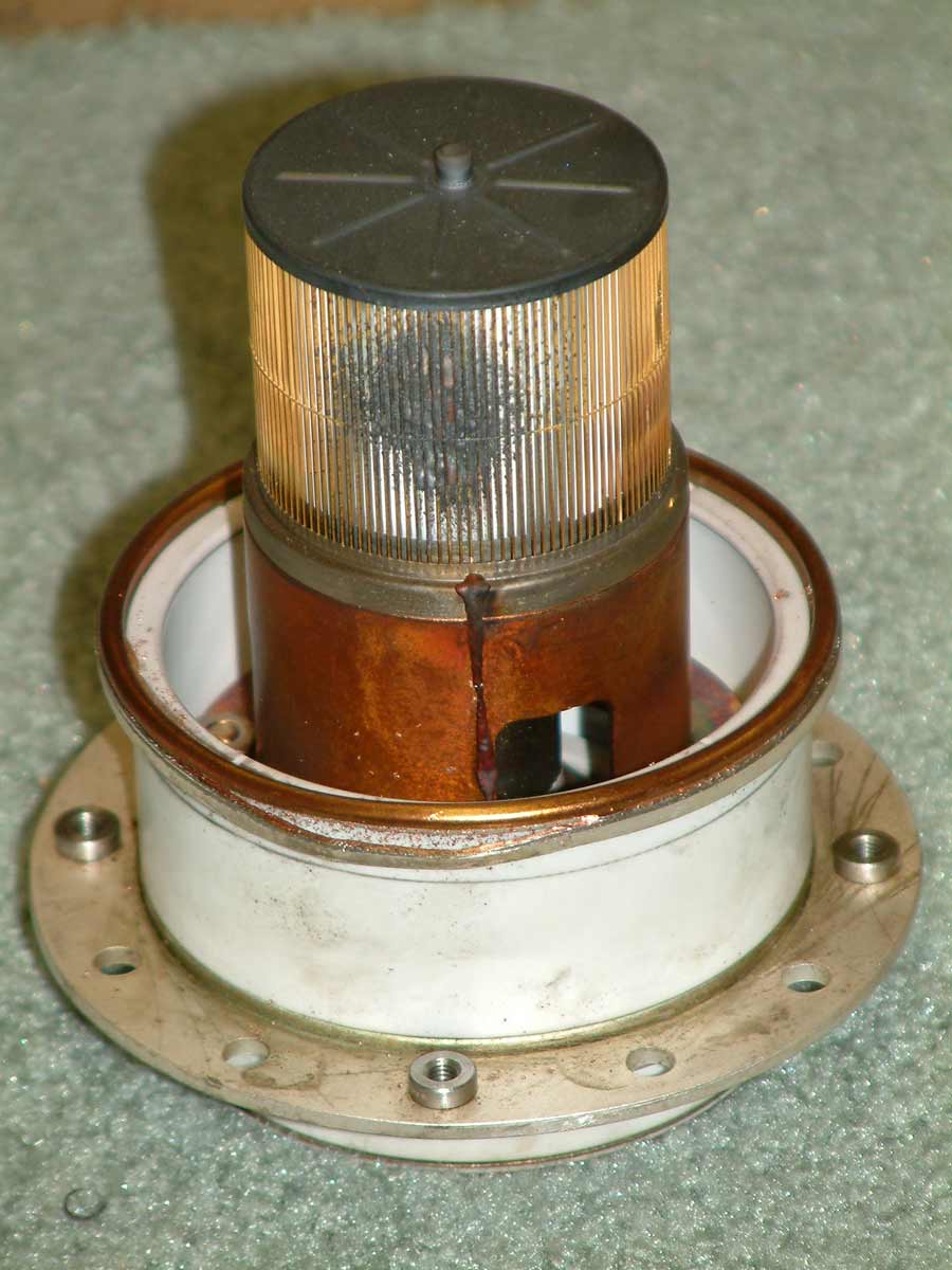
The following picture is the grid of a YC156/3CPX5000A7 that was ruined by a single HV arc. The only fault protection was a string of 1 ohm 2 watt resistors:
Tubes that have "set up" for a while often collect gas. This gas either comes from slow leakage through tube seals or outgassing of tube elements. This is the number one problem with old vacuum tubes.
Another cause of leakage currents are deposits on the insulation inside the tube envelope. This can come from long filament hours on metal oxide cathode tubes. Cathode materials can migrate to the insulation and form a high resistance path.
The section below describes how to remove gas in old tubes.
Gettering is very important, since even miniscule amounts of gas will cause a low-resistance arc from anode to grid or cathode. The normal results of such arcs are blown grid chokes, collapsed anode chokes, damaged meter shunts, and other problems cause by high fault currents. While a few people blame high fault currents on parasitics, it is actually impossible for a parasitic to create such arcs. All the anode and grid can do is deplete the electron cloud from the area of the cathode, and the available current even with a parasitic is limited by the available emission. Uncontrolled arcs are always the result of gas or element alignment in the tube, rather than excessive current from oscillations.
Anode systems should have series-resistance to limit peak current in the event of a tube arc or failure. That series resistance should always be in the anode lead between the filter capacitors and RF choke. A diode clamp should be installed to protect meters, especially the grid meter since the grid is in the normal path of any internal tube arc.
Ceramic tubes, because of low anode operating temperatures, have the gettering agent applied to the cathode or filament assembly. This is the only area inside the tube that heats enough to activate most common gettering materials. Ceramic tubes without internal flaws or broken seals can generally be gettered by running the filament at rated voltage for an extended period of time before application of any high voltage. The normal time for gettering is between one hour and one full day. If the tube does not getter within a day it is most likely never going to be restored to a operational relatively pure vacuum.
Glass internal anode tubes generally have the gettering material coated on anodes, which must be operated a high temperatures to activate the getter. Glass tubes have a propensity for seal leakage and element out-gassing, both of which lead to a short self life for large tubes. It isn't the glass that leaks gas, but rather a Kovar alloy used to bond the glass to the metal protruding through the envelope.
Kovar is also subject to rusting. As odd as it seems, glass transmitting tubes should be stored in a dry location. Glass tubes should be operated at full temperature every few months.
Under some conditions a glass tube can be restored to operation by running low anode voltages and positive bias on the grid. This will sometimes allow full operating anode temperatures to be reached, and the tube can be "cooked" for several hours. I've had about a 50% success rate restoring old 3-500Z's that have sat for years without use. Even though they initially arced severely at full voltage, by cooking them at low voltage and positive grid bias to show anode color vacuum was restored.
Most important, an arc by itself will break down and getter gas inside the tube. This is why an amplifier with a gassy tube will sometimes operate without problem after a sudden tube arc.
Intentional arcing and overheating, while pumping down a tube, are often a normal part of tube manufacturing processes.
Filament life in vacuum tubes, like filament life in light bulbs is a complex function of operating hours, hot and cold cycles (thermal shock), mechanical shock, and temperature. Other than avoiding physical shocks to the tube, or cycling the filament off and on needlessly, temperature is the only variable we can control. We should be sure the filament is operated at or below the maximum recommended voltage.
In amateur service, filaments and heaters rarely (if ever) are operated enough hours to have operating-time related failures. Most tube filament failures are mechanical failures, more related to constant on-and-off cycling of the tube than wear from extended hours of conservative operation.
Mechanical issues such as material or assembly defects can combine with close element spacings inside the tube, and cause failures. With spacings in thousands of inches, even the slightest change in physical shape or positioning filaments or cathodes can create a grid-to-filament (or cathode) shorts. Material quality and manufacturing techniques by tube manufacturers are critical to tube life, and sometimes mistakes are made.
Some claims are made that oscillations can cause filaments to bend, but there isn't anything that even remotely supports such claims.
For example, the normal peak filament current of a sine-wave powered 3-500Z filament is about 1.414 times 15-amperes, or 21 amperes. The total force on the filament helice is 11 grams distributed over a 7 cm area for this 21-ampere current in the typical helical structural dimensions of the filament.
The small additional force of a fully saturated emission condition (which requires around 1000 volts of positive grid voltage) results in only 30% increase in total bending force, hardly significant in any filament robust enough to last years in normal operation. Not only can the peak current not reach fatal levels though any type of emission, the grid-cathode potential is not able to reach levels required to saturate filaments.
In order for any tube under any condition to draw more than the peak saturated current, operating potential has to exceed the breakdown voltage of the tube.
There are two reasons excessive current might flow between elements in a tube:
The peak anode supply voltage exceeds the hold-off voltage of the tube, causing a good tube to arc
The tube may be defective either through gas or an incorrectly located anode or grid
Either of these conditions would allow an internal arc, with fault current limited mostly by external circuit resistances. Oscillations, like normal drive power, can only take a healthy tube up to the saturated emission limits. Even then it would take hundreds or thousands of grid-cathode volts to saturate the emission, an impossible condition unless someone drives a 3-500Z mistakenly with a 4CX5000 or some other large PA!
There is a special condition where tubes can fail, and that is where excessively high voltage components are used in tank systems. Under load fault conditions, when nothing absorbs energy supplied to the tank and tank components do not saturate or breakdown, the tube peak anode voltage can reach levels where an arc occurs in a healthy tube. See the load faults and tuning section, and the practical demonstration areas of this website.
Tubes are relatively robust components, but they are one of the primary points of failure in any electronic device that uses tubes. While many of us would like to believe we can make small circuit changes to prolong tube life, the fact is most tube failures are related to material or construction problems within the tube. In amateur service, most failures relate to manufacturing problems in the tube.
Out-gassing and seal leakage are particularly troublesome in glass tubes, since porous anodes and imperfect glass-to-metal seals allow miniscule amounts of gas to enter the vacuum.
Keep seals below rated temperature
Avoid long periods of excessive anode or grid dissipation
Avoid extended periods of non-operation
Avoid filament voltage OVER the manufacturer's rating
Do not excessively cycle the filament
Do not subject the tube to shock or vibration
Use some form of reliable fault-current limiting in the anode
Keep seals below rated temperature
Avoid long periods of excessive anode dissipation
Avoid even very short periods of excessive grid dissipation by including a fast electronic grid-trip circuit
Avoid filament voltage OVER or UNDER the manufacturer's rating
Do not excessively cycle the filament
Always allow full warm-up before allowing any cathode current to flow
Never apply excessive high voltage, as it may strip or poison the cathode
Do not subject the tube to shock or vibration
Use some form of reliable fault-current limiting in the anode
since Aug 2003