Balun Test Sleeve baluns Balun and Transformer Core Selection Verticals and Baluns Antenna Tuner Baluns Common mode current Common-Mode Noise toroid balun winding Steel wool balun
Two Modes of a Balun Line Transformer
There is a tendency to view a balun in much too simplistic terms. The most common errors stem from not fully understanding how the system terminating the balun behaves, and not understanding how that system interacts with the balun. We commonly consider only the load impedance or SWR, and of course RF power levels, when discussing baluns. Load impedance (or to a lesser detail SWR) describes differential (across the line) characteristic, and is easily understood and explained. Power is easily understood. The natural motivation to stay with what we easily understand is the root of misunderstanding baluns.
One of the most important things, the common mode voltage driving a balun or common mode impedance of a system, is largely misunderstood or ignored. Common mode impedance can really be almost anything from a few ohms to several thousand ohms, and is often unrelated to differential impedance. Perhaps common mode is ignored because it is a bit more complex, inconvenient to measure, and varies greatly even in what appear to be similar systems.
At times common mode excitation can be phenomenally high. One antenna design I've worked in particular on comes to mind, because it had the largest spread in voltage and impedance between common mode and differential (normal transmission line mode) mode I've ever observed. With a few hundred watts of power, with a differential mode impedance of 50 j0 and 1:1 SWR, the common mode voltage driving the balun in this troublesome system was several thousand volts. String of beads 50 beads long would literally shatter or melt through Teflon coax (even though the SWR was 1:1) with only a few hundred watts of transmitter power.
In contrast to that system, I worked on a small "magnetic" loop antenna. The small loop presented a very high common mode impedance with almost no common mode voltage, and even though the loop was a balanced system a good balun made absolutely no difference in performance or common mode current. For any feed line length, with or without a balun, common mode current on the feed line to the loop was essentially zero.
In the above systems, the first example (the dipole) could be much worse than a balanced balun test load simulated by a center-tapped resistor. The second case, the very small "magnetic" loop, appeared to the feed line almost like a fully floating resistor. This points to one very real conclusion, a balun test with a fully floating resistor is like the testing the balun in a system were the balun is not needed; a system where the balun serves no useful purpose.
The amount of current that flows into the feeder as common mode is determined by the common mode impedance looking back down each conductor of the feed line, and the electrical potential that drives that impedance. The antenna terminals in effect push back against the feed line, just like it is a generator. The other "foothold" is the electrical mass or common mode impedance of the antenna itself, as the antenna behaves like a radial or counterpoise working against the feed line. In general very large symmetrically fed half-wave antennas have a very low common mode impedance near the antenna. This is because in common mode, a half-wave dipole looks like two opposing 1/4 wave radials! The dipole presents a pretty stiff source voltage at the feed line terminals. Each conductor in the feed line is effectively driven by a voltage that is around half the voltage appearing across the antenna's feedpoint, the electrical mass of the antenna being the footing to push current down into the feed line.
(Asymmetrical antennas, feed lines that parallel or run inside elements (like end-fed dipoles or skirt vertical dipoles), and many other systems generally drive the feed line from a common mode voltage source that is much higher than the voltage across the feed line from conductor-to-conductor.)
Looking at it this way it is easy to see why the small balanced loop develops very little common mode current under any feed line length condition, and why a dipole can significantly excite the feed line. The loop has a very high common mode impedance, not nearly as low as a small floating resistor, but still high enough make the loop act like a poor counterpoise. This makes it difficult to push common mode current into the feed line. The dipole on the other hand looks like a pair of 1/4 wave radials, each providing a very low impedance for common mode voltages to push against and drive current into the feed line conductors. On the test bench, the center tapped resistor that is grounded at the center is very close to a dipole. Common mode current and imbalance in the antenna (or center tapped load) is limited primarily by the common mode impedance looking into the source (the feed line or balun). In a balanced line, both conductors are excited with common mode. An unbalanced line, the coaxial feed line, behaves in common mode as a single-wire transmission line with the shield as the sole conductor.
It's easy to see the actual load a balun (or transmission line) connects to varies over quite wide extremes in common mode. The load on the balun or transmission line almost never appears as a small floating resistor. In a very small small loop, the antenna behaves like a resistor divider with one side going to a small capacitance. In other cases, like the half-wave dipole example, the load on the balun (or feed line) appears similar to a center tapped 50-75 ohm resistance.
One of the worse jobs in the world is to design a balun that behaves properly in all installations at an advertised power rating. As a matter of fact, it is impossible to have a power rating that applies to all situations. A balun that works great in one application can greatly misbehave in another.
For example, a low-loss core high-Q core (i.e. air or a low permeability iron or ferrite) can handle a great deal of power without heating, but it is also the least reliable core for suppression of common mode. A high-Q core that never heats is often not effective in balancing currents, and can actually increase common mode currents and decrease system balance.
If I wanted a balun that would never get hot, I would use a core that had virtually no common mode suppression at all! Consider the case of a balun with a 10 +j1000 ohm common mode impedance, as we might find in a large air-core balun with a common mode Q of 100. If the common mode impedance at the insertion point is anything above -j500 ohms in reactance, the balun will actually increase imbalance and unwanted common mode current!! This is why I never use air-core baluns unless I understand the system the balun is being used in, and I know the system is compatible with that style of balun.
Only one type of impedance will always suppress common mode under any system condition. That impedance is a pure resistance. Adding a pure resistance in series with any common mode impedance, no matter what the reactance might be, will always reduce common mode current. We cannot say the same thing for high-Q chokes.
The transformer or winding in the balun has two distinct functions:
It can act as a transmission line, conveying energy along the parallel path of the two conductors in the windings, carrying the differential mode (transmission line mode) signal to the load as any transmission line would. In this mode the core has minimal effect if any. The core could be replaced with anything from air to steel with very little effect on performance. The small effect that might occur comes because the transmission line in the balun is less than perfect. There will be a small amount of electric and magnetic flux outside the area of the parallel wires, and those fields often impinge on the outermost surface area of the core and other conductors or dielectrics outside the conductors making up each specific area of transmission line. This is the differential mode of the transformer windings, where two conditions are met:
1.) Voltages at any point along the transmission line are of opposite polarity from conductor to conductor.
2.) Conductor currents, at all points, are traveling in opposing directions in any section of the transmission line.
It can act like a conventional transformer, conveying energy through direct electric or magnetic field coupling (or a mixture of both) between conductors. In this mode the core has a significant effect on frequency response and efficiency. The core, depending on frequency, has a major impact on impedance and performance, often having the greatest impact on system impedance at lowest operating frequencies and system losses at all operating frequencies. This is the common mode of the transformer windings, where one or more of following three conditions are met:
1.) Voltages between conductors at any point are the same polarity.
2.) Currents in each conductor at any point are not equal or are not flowing in opposite directions.
3.) One conductor in the parallel winding acts a source that drives an external load. This is the secondary winding. The other conductor in the winding acts as a load for an external power source. It is excited end-to-end in one winding conductor, and is the primary winding.
Most transformers or windings in a balun act a bit like both modes. The general system design goal is to have the transmission line effect be most important, because it is the mode where the balun is most easily made to have the widest bandwidth and lowest loss.
Dipole Antenna Model
The following is an example of how severe the stress on a balun can get, and why feed line length must be adjusted to provide moderate impedances to baluns. This model is for an 80-foot high 1/2-wave 80 meter dipole with 1.2 inch spaced balanced line with thin polyethylene insulation on each conductor.
This is the 80-foot high 80-meter dipole over perfect ground.
This is a zoom of the feedpoint. Distance of wire 7 (from 5 to 6) is one foot. In order to feed the antenna and not violate model guidelines, I had to spread the feed line wires from 1.2 inches out to 1 foot. I shorted the feed line wires with wire 7, and inserted a current source in number 7 set for the current produced by 1000 watts of power into the feed line.
The current source in a model is perfect, being totally independent of ground.
Wire 8 is used to test common mode in a balun, in this case assuming a current balun.
Let's look at what happens in the balun with common mode.
Across the source at 7 we have:
| EZNEC+
ver. 5.0 ladder line dipole 6/6/2010 7:17:54 PM --------------- SOURCE DATA --------------- Frequency = 3.6 MHz Source 1 Voltage = 1942 V at -63.0 deg. Current = 1.134 A at 0.0 deg. Impedance = 777 - J 1525 ohms Power = 1000 watts SWR (50 ohm system) = 75.441 (400 ohm system) = 9.837 |
We have 1942 V RMS differential mode voltage. This is what excites the transmission line in a 1:1 balun, and what appears from terminal to terminal.
In common mode from the left terminal with a 5000 j0 common mode impedance balun we have:
| EZNEC+
ver. 5.0 ladder line dipole 6/6/2010 7:05:40 PM ---------- LOAD DATA -------- Frequency = 3.6 MHz Load 1 Voltage = 781.6 V at -49.31 deg. Current = 0.1563 A at -49.31 deg. Impedance = 5000 + J 0 ohms Power = 122.2 watts Total applied power = 1000 watts |
With a difficult-to-obtain 5,000 ohm j0 common mode balun impedance, the cores would dissipate 122 watts or 12.2% of applied power.
There are two ways to fix this, make the balun primarily reactive or alter the feed line length.
Looking at a slightly reactive balun common mode from using a higher Q core:
| EZNEC+
ver. 5.0 ladder line dipole 6/6/2010 7:37:01 PM --------------- LOAD DATA --------------- Frequency = 3.6 MHz Load 1 Voltage = 815.4 V at -43.32 deg. Current = 0.1939 A at -61.32 deg. Impedance = 4000 + J 1300 ohms Power = 150.3 watts Total applied power = 1000 watts |
We can see that balun core dissipation would now increase to 15% of applied power. Current unbalance would also increase considerably from .156 amperes to .1939 amperes.
| EZNEC+
ver. 5.0 ladder line dipole 6/6/2010 7:44:35 PM --------------- LOAD DATA --------------- Frequency = 3.6 MHz Load 1 Voltage = 1254 V at -57.69 deg. Current = 0.2508 A at -146.54 deg. Impedance = 100 + J 5000 ohms Power = 6.292 watts Total applied power = 1000 watts |
Balun common mode current is up to .25 amperes, the highest value yet. Balun heat would be down to a cool 6 watts. This balun core would barely get warm.
The above is NOT WORSE CASE, just a random case I picked from typical feed line lengths. It is possible for all of these numbers to get worse, and for the addition of a high-Q balun that is primarily all reactance to seriously unbalance the antenna system. This is true even with a very high reactance! Many times a cool-running balun is a sign of a balun not doing its job.
Typical 80 meter Doublet on 40 Meters
The typical 80-meter dipole or doublet on 40 meters with a 65 foot long feed line is an example of another stressful load for a balun.
|
ladder line
dipole 6/8/2010
11:10:04 AM --------------- SOURCE DATA --------------- Frequency = 7.2 MHz Source 1 Voltage = 2137 V at -28.56 deg. Current = 0.5329 A at 0.0 deg. Impedance = 3522 - J 1917 ohms Power = 1000 watts SWR (50 ohm system) = 91.305 (400 ohm system) = 11.439 |
ladder line
dipole 6/8/2010
11:10:04 AM --------------- LOAD DATA --------------- Frequency = 7.2 MHz Load 1 Voltage = 899 V at -36.6 deg. Current = 0.1798 A at -36.6 deg. Impedance = 5000 + J 0 ohms Power = 161.6 watts Total applied power = 1000 watts |
By not changing height of the antenna, and only changing feed line length to 99 feet (from 1/2 wave above to approximately 3/4 wavelength), we have the following:
|
ladder line
dipole 6/8/2010
11:30:50 AM --------------- SOURCE DATA --------------- Frequency = 7.2 MHz Source 1 Voltage = 494.3 V at 53.91 deg. Current = 3.434 A at 0.0 deg. Impedance = 84.78 + J 116.3 ohms Power = 1000 watts SWR (50 ohm system) = 5.287 (400 ohm system) = 5.134 |
ladder line
dipole 6/8/2010
11:30:46 AM --------------- LOAD DATA --------------- Frequency = 7.2 MHz Load 1 Voltage = 202.1 V at 53.82 deg. Current = 0.04041 A at 53.82 deg. Impedance = 5000 + J 0 ohms Power = 8.166 watts Total applied power = 1000 watts |
Balun core heat is reduced from 162 watts or 16% of transmitter power, to 8 watts or 0.8% of transmitter power. feed line length is critical to optimum balun performance. While it isn't always the case that balun heat or core stress is always low with a low terminating impedance on the balun, it is generally true that balun core stress always increases with load impedance terminating the balun.
I only use an air-core choke balun in very specific applications where I know what the effect will be. When the system is unknown, I use a core that produces a primarily resistive common mode impedance. If the balun overheats, I alter feed line length. This will often correct the problem without changing the balun's design.
Some entire balun handbooks and many articles have been written without an understanding of how the balun actually interacts with the antenna system. The truth is... if a balun never overheats at high power in any application, it may not be acting like a balun at all with real loads. Some baluns appear perfect on the test bench while failing to balance many real-world systems.
Range of Common Mode Impedances
One way to measure common mode impedance is to short the feed line terminals and feed the system as a single wire antenna. Here is the common mode impedance of another 80-meter doublet or dipole fed with 99 feet of open wire line on 40 meters.
| -- common mode source
impedance-- Frequency = 7.2 MHz Impedance = 98.86 - J 272.3 ohms |
5000 j0 CM balun losses Load 1 Voltage = 216.4 V at -123.54 deg. Current = 0.04327 A at -123.54 deg. Impedance = 5000 + J 0 ohms Power = 9.363 watts Total applied power = 1000 watts Total load power = 9.363 watts Total load loss = 0.041 dB |
--differential mode SOURCE
DATA -- Frequency = 7.2 MHz Source 1 Voltage = 480.7 V at 53.82 deg. Current = 3.524 A at 0.0 deg. Impedance = 80.52 + J 110.1 ohms Power = 1000 watts SWR (50 ohm system) = 5.045 (400 ohm system) = 5.359 |
We see that when common mode and differential source impedances are low, a balun can do a very effective job. feed line common mode impedance can range from a few ohms to several thousand ohms, and this impedance critically affects balun and system performance. If we insert a balun at a point driven with very high voltages balun heating can be catastrophic. If the balun doesn't heat, from inadequate common mode impedance or being largely reactive, the system will often just go out of balance.
4:1 Transmission Line Balun with Balanced Load
The circuit below shows a 4:1 transmission line current balun in operation feeding a balanced load. This balun is a 4:1 ratio and feeds a balanced 200-ohm load. This load would be very similar to the terminal impedances of a full-size perfectly symmetrical antenna, like a folded dipole, a large and perfectly symmetrical loop, or a symmetrical "T" matched antenna with a feed line length that is neither worse case nor optimum feed line length. The load resistors have to be grounded in the center for one simple reason. For any system to be perfectly balanced, or for a balanced transmission line to not radiate, line currents have to be exactly equal and opposite and voltage with respect to the outside world has to be exactly equal and opposite at any and all points along the system. Many people miss this, and think the only requirement is having equal and opposite currents at one point in the system is enough to ensure full system balance.
Another serious flaw is testing a balun or analyzing a balun using a floating load, like a physically small resistor placed across balun output terminals. One popular UnUn and Balun handbook shows a lack of understanding of how to analyze, measure, and test baluns! It actually suggests power is evenly divided between the two choke baluns making up a 4:1 current balun. Nothing is further from the truth! Most likely the misconception that the transformers share equal dissipation comes from a lack of understanding of field theory and antenna systems, especially common mode impedances.
Let's look at power dissipation using a SPICE model. Logic tells us with an infinite common mode load impedance (R5), like a physically small resistor, balun voltage and heating will be equal in each winding:
This model uses a 10 million ohm common mode impedance, allowing the magnetizing impedance in transformers T1 and T2 to determine voltage division. With equal transformers, voltage will divide evenly. This is the flawed case used by some balun designers and published in some balun handbooks and white papers.
We see the model agrees with theory.
Balun upper and lower terminal voltages are in a 3:1 ratio, and the sum of voltages equals balun source voltage.
Balun core dissipation would only be 1/2 watt in each core with 200 watts delivered to the 200-ohm load.
Core heating and dissipation is evenly split.
Now let's look that the upper extreme common mode impedance likely to occur in real-world systems:
In this case we set common mode Z at 5000 ohms. This would be similar to a 1/4 wave long open wire line feeding a large matched balanced load, like a folded dipole antenna.
Upper terminal R3 top is 133.2 volts.
Lower terminal voltage is now 66.44 volts, now a ratio of only 2:1 in voltages. Balun cores are now unevenly heated, with 223 mW dissipation in the top core (T1) and 883 mW dissipation in the bottom core (T2).
This is still a successful balun because the applied voltage is so low, but it demonstrates how uneven core heating increases rapidly with very slight amounts of common mode current. T2 heats four times more than the other core, T1!
Running through the model again but with a 650-ohm common mode impedance, a very typical middle for common mode impedance, we again find uneven core heating becomes a problem. The system has only 21 milliwatts in T1, and 1.61 watts in T2. This is a core heating ratio of 77:1 between the two core!!! The upper core barely does anything.
A second factor in heating is the voltage across the load resistance, R3 and R4. In this case we only have 200 volts across the resistors because we have a 1:1 load SWR (200 ohm load across an assumed 200 ohm balun output) at 200 watts. If the feeder has a high SWR, like a 450-ohm line feeding a dipole or doublet antenna, and if we pick a combination of antenna and feed line length that present a high load impedance to the balun, we can have severe balun heating problems even with modest power. This is because balun core losses are so high.
This tells us there are two general rules for minimizing balun heating:
- Common mode impedance should be as high as possible on the balun output.
- Differential mode impedance should be as low as possible across the balun output.
We can also conclude any balun test that assumes equal distribution of losses between cores is an impossible real-world situation. There isn't an antenna system anywhere that has an infinite common mode impedance, and virtually every system is under 5000 ohms common mode impedance. Most antenna systems are probably 1000 ohms or less common mode impedance, so we can just ignore any contribution of the upper transformer to power handling.
This also excludes the idea that a dual transmission line balun like a 4:1 can use a single core, an idea that was promoted in a popular Balun and UnUn handbook. The flawed idea the load looks like a floating resistor results in all sorts of misunderstandings about balun behavior.
My Earlier Simple Models and Analysis
This is an earlier model I used, and the method I use on the test bench here. It is easy to see it is much closer to the real world than the floating resistor (infinite common mode impedance) model. As a matter of fact if every system presented infinite common mode impedance to the balun, there would be no need for baluns in any system!
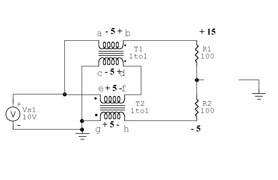
In this balun, the transmission line transformers clearly behave in two very distinct modes. They act as 1:1 transformers, and they also act as transmission lines. In the first example, one of perfect balance, the transmission line transformers operate primarily as transformers. T2 is excited across e-f by 10 volts with g-h being the secondary, while T1 is excited by theoretically exactly equal and opposite currents in the windings and thus has zero core flux density.
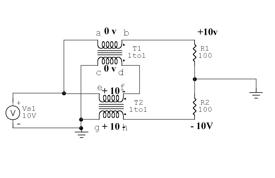
T1 voltages and currents:
Current flowing through a-b is 0.1 ampere
Current flowing through c-d is 0.1ampere in the opposite direction
This results in zero voltage across a-b and c-d
Volt-turns in T1 is zero under a perfectly balanced condition, since current in windings flows opposite directions. R1 current through a-b is equaled by T1 from d-c, so ampere turns magnetizing the core oppose each other. T1 has no flux in core, since volt-turns = zero. T1 can be shorted from a-b or from c-d with no effect.
T2 voltages and currents:
e-f has the same current as flows through c-d, c-d has the same as a-b, 0.1 ampere
g-h must also have the same current as flowing through e-f
R2 has equal current with R1, 0.1 ampere
this means g-h has 10 volts, phase as shown
Ampere turns (flux density) in T2 is R2 current times turns. T2 core carries all the flux in a balanced-voltage balanced-current (perfect balance) condition.
Real Transmission Line 4:1 Balun Unbalanced Voltage R1 top =0V
The same balun with perfect unbalance in load, top grounded:
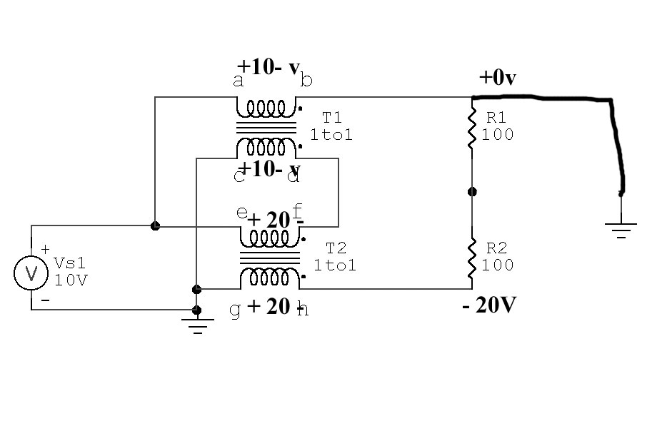
In this case we new voltages.
T2 now has twice the volt-turns of T1, and with equal windings and cores this causes flux density in T2 to be twice that of T1.
T1 cannot be replaced by a short from a-b or c-d.
T1 is now required to allow voltage at top of R1 to deviate from the original +10 volts, in this case reaching 0 volts. . Shorting a-b or g-h would now prevent proper operation.
Real 4:1 Transmission Line 4:1 Balun Bottom Grounded
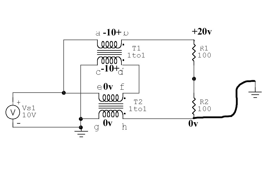
Now we see flux density in T2 is zero.
g-h or e-f can be shorted
Flux density in T1 is maximum, flux in T2 is zero.
Single-Core Dual Transmission Line Balun
It has been proposed in a few places that a single core can be used to create two 1:1 choke baluns in a transmission line balun, and this will still create a good current balun. We cannot combine cores unless each transformer has IDENTICAL flux density under all conditions of load balance.
Here's what happens to our baluns above if we have a single core that provides a closed path for all flux from all windings:
With identical turns on each winding and a common core causing equal flux levels to pass through every winding, voltage across each winding would be held equal. This means any solution of voltages to the load must provide:
The sum of voltages from c to e must equal supply voltage
Output voltage across load is now 20v, so we have a correct 4:1 impedance ratio but:
Load is voltage unbalanced, that means if we ground center tap or either end of the load we upset voltages and currents in the system. We no longer have a balun, we have an unbalanced voltage source.
Any tolerance of the three balance conditions a current balun must maintain would only occur if the core had flux leakage. The worse the core, the better the balun will behave.
The book Baluns and UnUn's proposes a transmission line balun like the balun above could be wound on a single core. That isn't true. A balun configured as shown to the left must be on two separate cores or it will not remain balanced. We cannot hold each core to the same flux density or the load will be seriously unbalanced.
The source end of the transmission line must always be fed with equal and opposite currents, and must always have the source applied in differential across the line at the input (source end) only.
In a transmission line (excited as shown above) energy is conveyed from end-to-end in a TEM mode. This mode requires, under the conditions of matched load, voltage between conductors along the line to be in a precise relationship with current. In the case of a 50 ohm line with 50 watts, current (through vector) would be 1 ampere while voltage (across vector) would be 50 volts. This is true anywhere along the line.
If we mismatch the line, the product of voltage across and current through the line at any point is still 50, even though the ratio of E to I will change.
We have two conditions then that apply to any load.
- In a matched condition voltage across and current through at any point are always in the same ratio, and that ratio equals line impedance and the product always equals power applied. Transmission currents in the two conductors are always exactly equal and opposite at any single point along the line.
- In a mismatched line the voltage across and current through the line at any point has a vector product equal to power applied, and the ratio of voltage and current at any point is equal to the line operating impedance at that point. Transmission currents are always equal and opposite.
Here is a way to have equal currents but not be in a transmission line mode:
If we take the output from the conductor normally used as the opposing conductor in a transmission line, we still have opposing current directions. The electrical equivalent of this "transmission line" circuit is shown here:
This obviously is not a transmission line mode, but instead is a simple basic primary/secondary transformer.
Let's see if this system follows the same rules as a transmission line in TEM mode.
Notice in all cases above voltage across the line at any and all points is zero. This means no energy is conveyed along the line in TEM (transmission line) mode, even though currents are exactly equal and opposite. This system does follow the basic rules of a conventional transformer, in that the secondary ampere-turn product always equals primary-ampere turn product in order to keep secondary magnetic flux in equilibrium with primary flux density.
For example, if we have a lossless one turn primary and two turn secondary transformer with one ampere flowing in the primary, we know we must have 1/2 ampere in the two-turn secondary. This is independent of impedance between conductors.
In TEM mode, in a matched condition, the across and through vectors (E and I) at any point multiply to give us power flowing past that point. In "transformer mode", the product is zero because voltage between conductors is at any point is zero. We can change even "line impedance", and the change will have very little effect on SWR!
In transformer mode:
- Instead of energy being conveyed to the load by conduction currents flowing through a direct wired path (as in a transmission line balun), energy is now transferred through the "balun" via flux coupling between conductors. This means the balun core is at least partially involved in all energy transfer.
- The fact the core is directly subjected to magnetizing forces and is excited directly by source voltage greatly limits power/ mismatch range of the balun. A normal transmission line balun can tolerate extreme mismatches if proper materials are used, but the same size and quality materials in a transformer-style balun handle less power into matched loads, and significantly less power into highly mismatched loads.
- In a normal transmission line (even one used in a balun) the series inductance of the conductors is balanced by the shunting capacitance between the conductors. This means if we terminate the transmission line correctly, VSWR bandwidth is extremely wide.
since June 12 2005